Heat conductivity testing device

A thermal conductivity, testing device technology, applied in the direction of material thermal conductivity, material thermal development, etc., can solve the problems of poor repeatability and accuracy, inaccurate measurement, difficult to operate, etc., to reduce measurement errors, accurate measurement results, manufacturing strong effect

Inactive Publication Date: 2018-12-14
10TH RES INST OF CETC
View PDF8 Cites 29 Cited by
  • Summary
  • Abstract
  • Description
  • Claims
  • Application Information

AI Technical Summary

Problems solved by technology

The disadvantage is that it is only suitable for isotropic, homogeneous and opaque materials, the repeatability and accuracy are relatively poor, and the influence of human factors is obvious
[0004] The steady-state heat flow method is a relatively popular measurement method in the world. In the prior art, the shortcomings of the thermal conductivity tester using the steady-s

Method used


Image

  • Heat conductivity testing device
  • Heat conductivity testing device
  • Heat conductivity testing device

Examples


Embodiment Construction

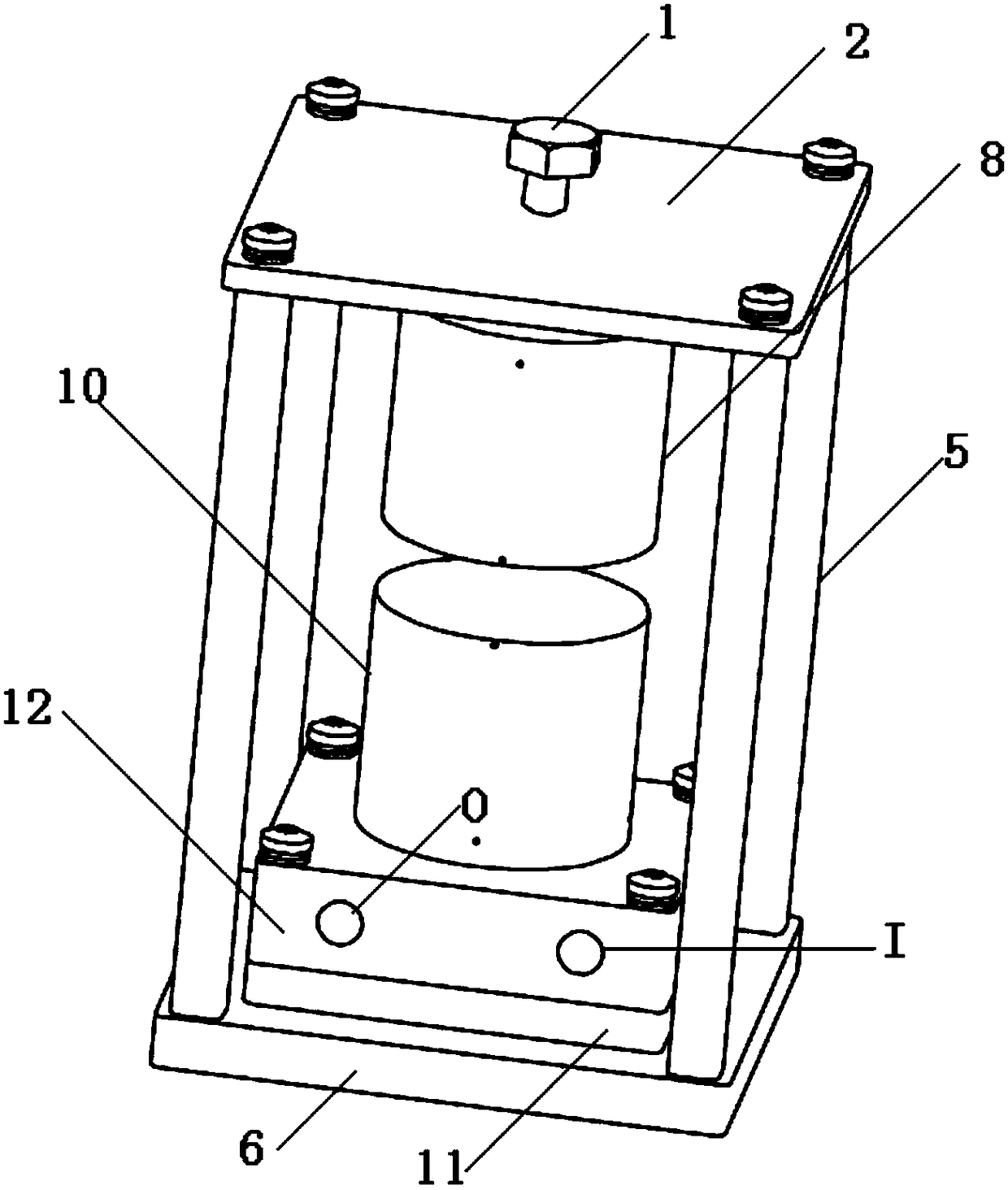
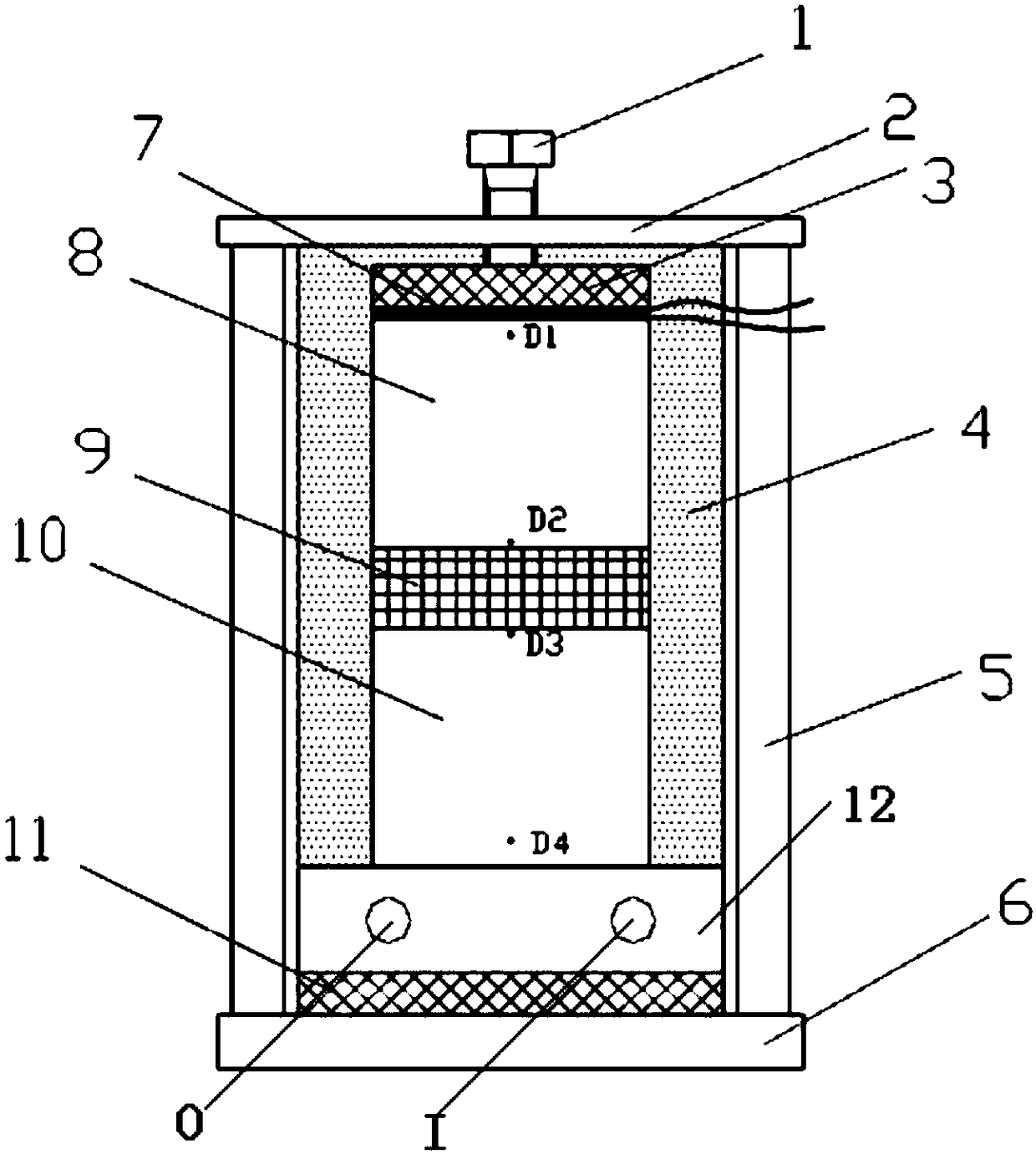
[0017] refer to figure 1 , figure 2 . In the embodiment described below, a thermal conductivity test device includes: a heating metering unit, a heating protection unit and a cooling unit, and a test bracket composed of a column 5 fixed circumferentially between the top plate 2 and the base 6, and the test The bracket is composed of 4 circumferential columns fixed on the top plate 2 and the base 6 . The cooling unit includes a heat dissipation cylindrical disk 10 fixed on the base 6 . The heat dissipation cylindrical disk 10 and the lower heat insulating pad 11 are installed on the base 6 , and the test sample 9 is placed in the measurement cavity between the upper surface of the heat dissipation cylindrical disk 10 and the lower surface of the heat source cylindrical disk 8 . The heating part is composed of a sheet-shaped electric heating source 7 arranged on the top of the heat source cylindrical disk 8 , the sheet-shaped electric heating source 7 is pasted on the surfac...


PUM


Abstract

The invention discloses a heat conductivity testing device, and aims to provide a device which is stable in control of the heat sink temperature and accurate in measurement at temperature testing points. The heat conductivity testing device is achieved by a technical scheme as follows: a cooling unit consists of a rectangular liquid-cooling circulating heat sink cold plate positioned at the bottomend of a heat-dissipating cylindrical disc and integrally formed together with the heat-dissipating cylindrical disc; a heat source cylindrical disc, and a sheet-shaped electric heating source and anupper heat-insulating cushion block which are assembled at the top end thereof, and the heat-dissipating cylindrical disc are coaxially enwrapped in an insulation layer; after a heat source with known constant power is used for heating till a steady state, by virtue of the heat conductivity lambda of a measured material, and according to known heat conductivities of materials of a heating metering unit and the cooling unit, temperature values of testing points D2 and D3 forming gradient distribution in the direction perpendicular to the surface of a test sample are detected through twice measurement, the heat flux Q of the test sample and the temperature difference deltaT between the two ends of the test sample 9 are worked out by using a heat conduction law Fourier formula, and the heatconductivity of the test sample is calculated.

Description

technical field [0001] The invention relates to a method that can test complex structural materials such as phase change materials, adhesive and tie materials, including thermal resistance of integrated chips connected to heat sink materials and thermal contact materials, thermal conductivity of multilayer materials and thin film materials, etc. the test device, Background technique [0002] In order to meet the miniaturization and lightweight requirements of electronic products, in order to improve the heat dissipation performance of electronic products, product designers and material researchers usually need to develop new thermal conductive functional materials for product structure design, and at the same time have good thermal conductivity. In the R&D and design stage of electronic products, it is necessary to use heat transfer theory to conduct theoretical analysis on the temperature distribution of electronic products, and to evaluate the rationality of thermal design...

Claims


Application Information

Patent Timeline
IPC IPC(8): G01N25/20G01N25/18
CPCG01N25/18G01N25/20
Inventor 李俞先胡家渝
Owner 10TH RES INST OF CETC
Why Eureka
Try Eureka