Isolation-type voltage collecting circuit
A voltage acquisition and isolation technology, applied in the field of isolated voltage acquisition circuit, can solve the problems of complex circuit, poor circuit consistency, slow response speed, etc., and achieve the effect of accurate acquisition results
- Summary
- Abstract
- Description
- Claims
- Application Information
AI Technical Summary
Problems solved by technology
Method used
Image

Examples
Embodiment 1
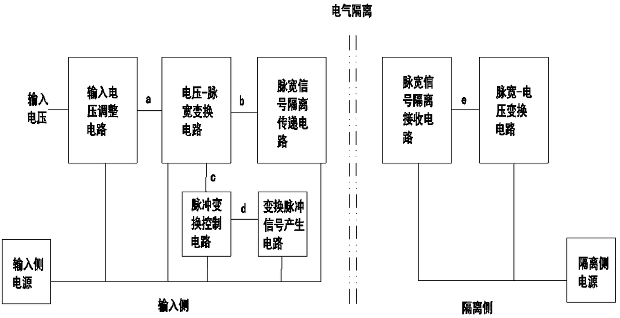
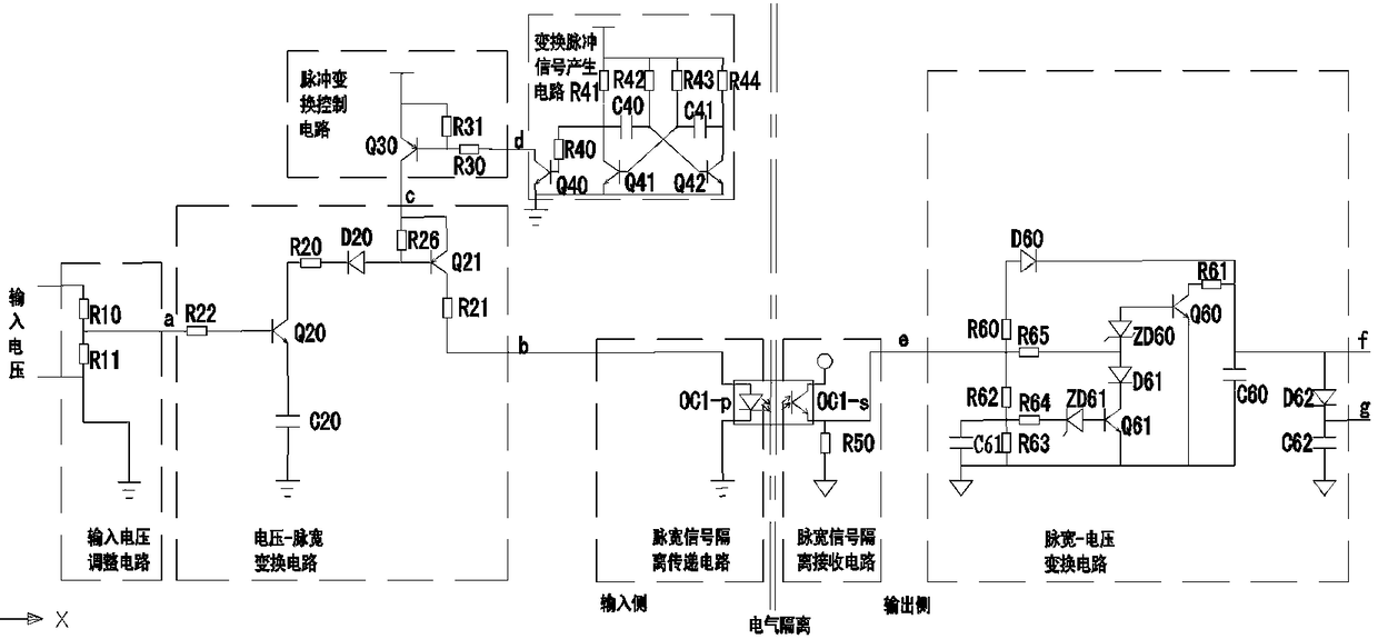
[0044] see figure 1 , figure 2 , an isolated voltage acquisition circuit, including an input voltage adjustment circuit on the input side, a voltage-pulse width conversion circuit, a pulse conversion control circuit, a pulse width signal isolation transmission circuit, a pulse width signal isolation receiving circuit on the isolation side, and a pulse width- Voltage conversion circuit, and conversion pulse signal generation circuit; all circuits on the input side are electrically isolated from all circuits on the isolation side, the input terminal of the input voltage adjustment circuit is connected to the input voltage, the input voltage adjustment circuit, pulse conversion control circuit and pulse width signal isolation transmission circuit Both are connected to the voltage-pulse width conversion circuit, and the conversion pulse signal generating circuit is connected to the pulse conversion control circuit; the pulse width signal isolation receiving circuit is connected t...
Embodiment 2
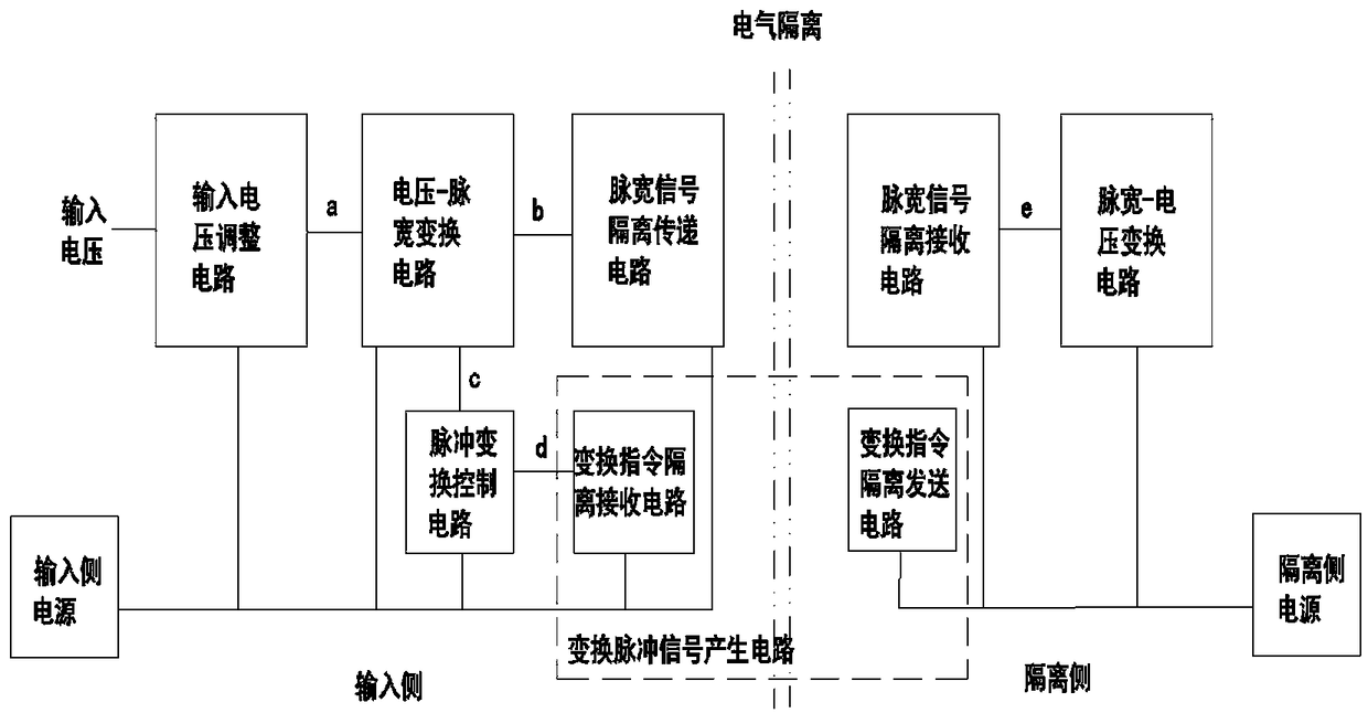
[0052] see image 3 , Figure 4 , The difference from the circuit of Embodiment 1 is: the conversion pulse signal generation circuit and the pulse width-voltage conversion circuit.
[0053] The conversion pulse signal generation circuit includes a conversion command isolation receiving circuit and a conversion command isolation sending circuit that are electrically isolated from each other. The emitter of the photosensitive transistor of the optocoupler OC2-s of the conversion command isolation receiving circuit is connected to the negative terminal of the input side power supply, and the optocoupler OC2 The collector of the phototransistor of -s is connected to the conversion pulse signal d; the anode of the light-emitting diode of the optocoupler OC2-p of the conversion command isolation sending circuit is connected to the positive end of the isolation side power supply through the resistor R45, and the light-emitting diode of the optocoupler OC2-p The cathode is connected ...
Embodiment 3
[0056] see Figure 5 , The difference from the circuit of Embodiment 1 is: a voltage-pulse width conversion circuit and an input voltage adjustment circuit.
[0057] The emitter of the NPN transistor Q20 of the voltage-pulse width conversion circuit is also connected to the collector of the NPN transistor Q22 through the resistor R23, the emitter of the NPN transistor Q22 is connected to the negative terminal of the input side power supply, and the base of the NPN transistor Q22 is The resistor R25 is connected to the anode of the diode D21, the cathode of the diode D21 is connected to the conversion pulse signal d, and the base of the NPN transistor Q22 is also connected to the positive terminal of the input side power supply through the resistor R24; when the conversion pulse signal d is a high voltage, that is, non-voltage -Pulse width conversion time, the NPN transistor Q22 is in the conduction state, the voltage across the capacitor C20 is discharged through the resistor ...
PUM
 Abstract
Description
Claims
Application Information