
A flattened luneberg lens antenna

A Lumberg lens antenna, flattening technology, applied in the direction of antennas, electrical components, etc., can solve the problems of high sidelobe, beam width, unable to meet practical application requirements, etc., to achieve basically the same performance, simple processing and manufacturing, superior performance. Effect

Pending Publication Date: 2018-12-14
NANJING HOWKING COMM TECH
View PDF0 Cites 12 Cited by
  • Summary
  • Abstract
  • Description
  • Claims
  • Application Information

AI Technical Summary

Problems solved by technology

At present, some researchers use metamaterials to realize the flat design of Lunberg lens antennas. Although this design method can realize the characteristics of Lunberg lens antennas in the beam converging plane, few researchers care about the non-beam converging Beam pattern for in-plane directions
During the design process of transforming the traditional spherical Luneburg lens into a cylindrical Luneburg lens antenna, it was found that the pattern of its non-beam converging surface showed the characteristics of wide beam and high sidelobe, which could not meet the actual application requirements. The design of Boer lens antenna becomes a new antenna design problem

Method used


Image

  • A flattened luneberg lens antenna
  • A flattened luneberg lens antenna
  • A flattened luneberg lens antenna

Examples


Embodiment Construction

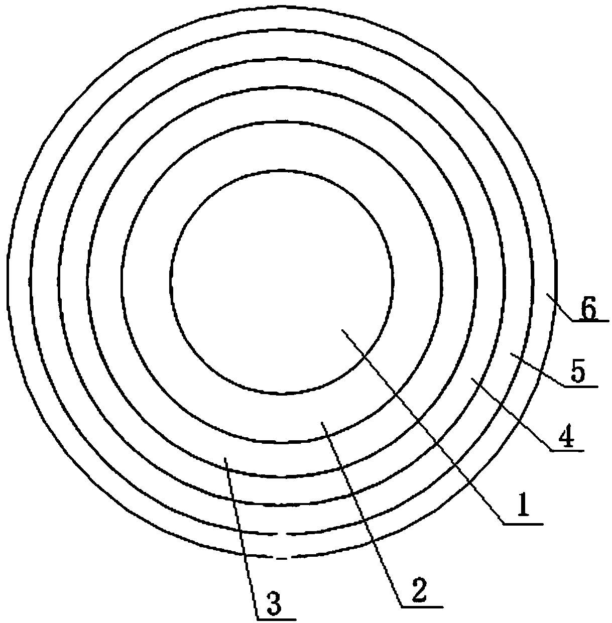
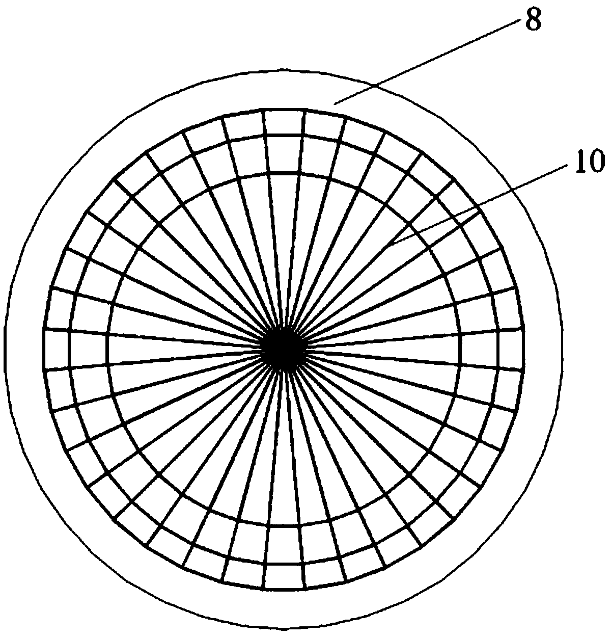
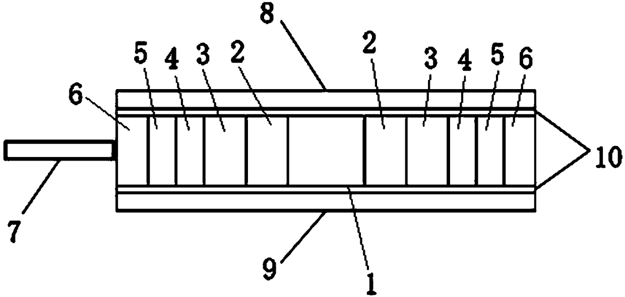
[0023] Such as Figure 1-4 As shown, the present invention discloses a flat Lunberg lens antenna, including a first medium 1, a second medium 2, a third medium 3, a fourth medium 4, a fifth medium 5, a sixth medium 6, a waveguide feed Source 7, first printed board 8 and second printed board 9, first medium 1, second medium 2, third medium 3, fourth medium 4, fifth medium 5 and sixth medium 6 from inside to outside Placed concentrically to form a cylinder, the waveguide feed 7 is located on the edge of the cylinder, and the first printed board 8 and the second printed board 9 are attached to the upper surface and the lower surface of the cylinder respectively. Wherein, the overall thickness of the cylinder is 20 mm. The waveguide feed 7 is 1mm away from the cylinder, and the first medium 1, the second medium 2, the third medium 3, the fourth medium 4, the fifth medium 5, and the sixth medium 6 converge the electromagnetic waves emitted by the waveguide feed 7 The effect is to...


PUM


Abstract

The invention relates to the technical field of antennas, in particular to a flattened luneberg lens antenna, including a first medium, a second medium, a third medium, a fourth medium, a fifth medium, a sixth dielectric, a waveguide feed source, a first printed board and a second printed board, the first medium, the second medium, the third medium, the fourth medium, the fifth medium and the sixth medium are concentrically placed from the inside to the outside to form a cylinder, the waveguide feed source is located at the edge of the cylinder, and the first printed board and the second printed board are respectively bonded to the upper and lower surfaces of the cylinder. While the flattened luneberg lens antenna of the invention realizes beam convergence in the E plane, in the H plane ofthe flattened luneberg lens antenna, due to the effect of a magnet ring of a loaded metal layer, electromagnetic waves are also close to the plane waves at the emergence end of the lens, compared with the case where the metal layer is not loaded, a directional diagram with a narrow beam and a low side lobe can be obtained in the H plane, and the performance is superior.

Description

technical field [0001] The invention relates to the technical field of antennas, in particular to a flattened Lunberg lens antenna. Background technique [0002] Lunberg lens antenna is a solution to realize high-gain antenna, and is widely used in multi-beam antenna scenarios. The traditional Lunberg lens is a concentric spherical structure with multiple layers of media with different node constants. This three-dimensional structure is difficult to process and can only be wrapped layer by layer from the inner layer to the outer layer. On the other hand, most multi-beam application scenarios are multi-beam in a one-dimensional plane, and there are few applications for two-dimensional multi-beam antennas. Therefore, the design of Lunberg lens planar Lunberg lens has a wide range of application scenarios. At present, some researchers use metamaterials to realize the flat design of Lunberg lens antennas. Although this design method can realize the characteristics of Lunberg le...

Claims


Application Information

Patent Timeline
Patent Type & Authority Applications(China)
IPC IPC(8): H01Q19/06H01Q15/08
CPCH01Q15/08H01Q19/06
Inventor 刘鹏飞陈平朱晓维张彦蒯振起
Owner NANJING HOWKING COMM TECH
Learn More