An efficient and environmentally friendly machining waste treatment equipment

A technology of mechanical processing and processing equipment, which is applied in the direction of cleaning machinery, cleaning equipment, manual sweeping machinery, etc. It can solve the problems of inconvenient recycling, inconvenient cleaning of waste debris, and many impurities in waste debris, so as to achieve rich device functions and convenient cleaning. Recycling and improving cleaning effect

Active Publication Date: 2021-03-05
江西佰嘉实业有限公司
View PDF9 Cites 0 Cited by
  • Summary
  • Abstract
  • Description
  • Claims
  • Application Information

AI Technical Summary

Problems solved by technology

[0003] Waste chips will be generated during mechanical processing, which needs to be collected and recycled. The existing waste chip collection device has a single function, which makes it inconvenient to clean the waste chips. The collected waste chips have many impurities and are inconvenient to recycle. Therefore, a An efficient and environmentally friendly machining waste treatment equipment

Method used


Image

  • An efficient and environmentally friendly machining waste treatment equipment
  • An efficient and environmentally friendly machining waste treatment equipment
  • An efficient and environmentally friendly machining waste treatment equipment

Examples


Embodiment 1

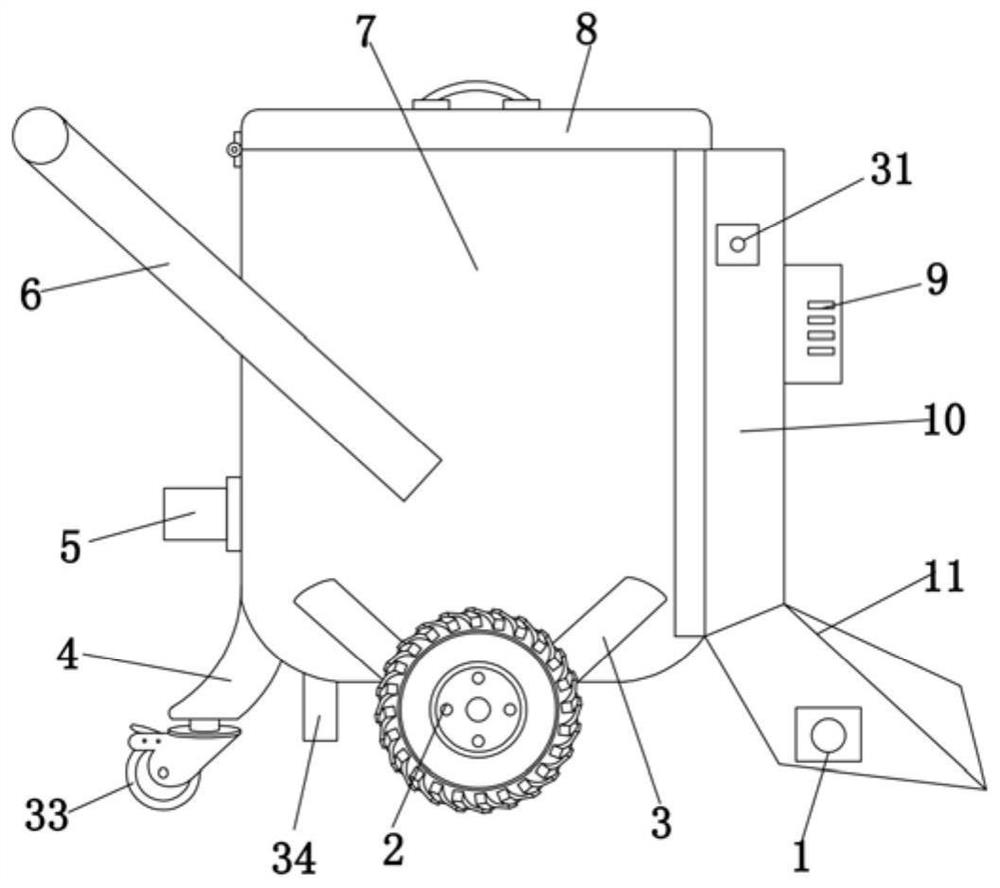
[0046] Example Figure 1-5 , A highly environmentally friendly mechanical machining waste treatment equipment, including metal cylinder 7, and the outer wall of the metal drum 7 is hinged in the outer wall 8, and the outer wall of the metal cylinder 7 is fixed by bolts 6, and the outer wall of the metal cylinder 7 The bracket 3 is welded, and the two stent 3 sides are active to be coupled with a wheel 2, and the metal cylinder 7 is facing away from the arm frame 6 side, and the suction mechanism includes a metal cover 10, and the metal cover 10 is welded. The suction bucket 11, the inner wall of the suction bucket 11 is provided with a cleaning mechanism 30, and the suction mechanism is fitted with the cleaning roller 17 to facilitate collecting waste to collect the waste on the machining ground, which is conducive to the preliminary screening of iron waste. It helps to increase the purity of the waste, the side wall of the metal cover 10 is fixed by the bolt, and the negative pre...

Embodiment 2

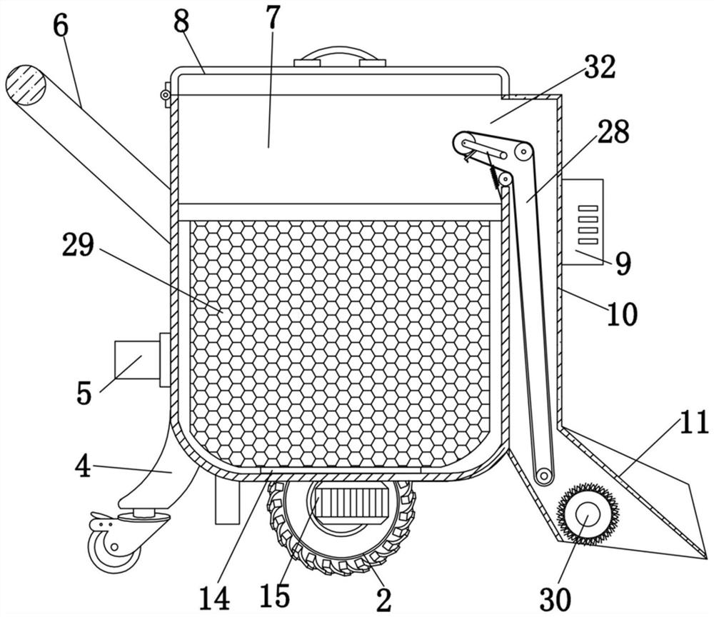
[0047] Example two reference Figure 1-5 The filter mechanism includes a first metal barrel 13, and the first metal barrel 13 side wall tip position is attached to the bearing ring 12, and the side wall of the bearing ring 12 and the inner wall of the metal cylinder 7 is close to the bottom of the feed hole. The first metal barrel 13 inner wall sleeve includes the second metal barrel 25, and the inner wall of the second metal barrel 25 welded to have a handle member 24, and the inner wall of the bottom end of the metal cylinder is fixed by the bolt, and there is a bearing turntable 14. And the top end of the bearing turntable 14 is fixed to the outer wall of the first metal barrel 13 by the bolt, and the intermediate position of the outer wall of the metal cylinder 7 is fixed by the bolt, and the third motor 15 output shaft passes through the bottom end of the metal tube 7. The inner wall and the first metal barrel 13 are fixed by bolt.

Embodiment 3

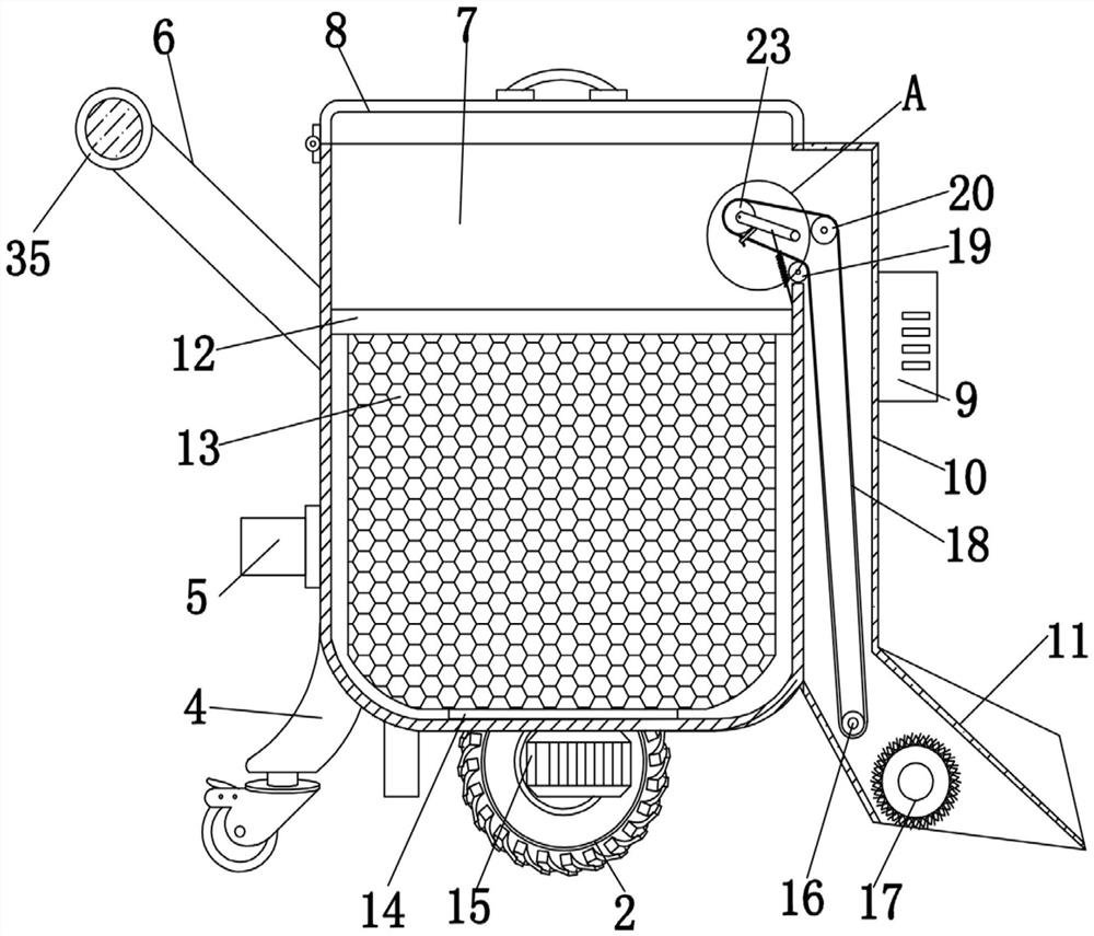
[0048] Example three reference Figure 1-5 The cleaning mechanism includes a cleaning roller 17, the cleaning roller 17 is attached to the inner wall of the suction bucket 11, and the sidewall of the suction strip 11 is fixed by the bolt, and the first motor 1 output shaft passes through the suction bucket 11 side outer wall The end of the cleaning roller 17 is fixed by a bolt.


PUM


Abstract

The invention discloses an efficient and environment friendly machining waste crap processing device comprising a metal cylinder, a cylinder cover is hinged on an outer wall on one side of a top end of the metal cylinder, a handrail frame is fixed on an outer wall on one side of the metal cylinder via screw bolts, support racks are welded on outer walls on both sides of the metal cylinder, and side walls of the two support racks are movably connected with a wheel; one side, positioned away from the handrail frame, of the metal cylinder is provided with a material sucking mechanism; the material sucking mechanism comprises a metal cover, a material sucking hopper which is arranged obliquely is welded on a bottom end of the metal cover, an inner wall of the material sucking hopper is provided with a cleaning mechanism, a negative pressure blower is fixed on a side wall of the metal cover via screw bolts, the negative pressure blower is communicated with the inner wall of the metal cover,and a first roller is movably connected to a top end of an inner wall of the material sucking hopper. The efficient and environment friendly machining waste crap processing device can be used for cleaning collected waste crap, device functions can be enriched, convenient recovery can be realized, the waste crap can be separated from other impurities, waste scrap purity can be improved, waste crapcan be conveniently driven to flip, waste crap cleaning effects can be improved, and waste crap is convenient to take out.

Description

Technical field [0001] The present invention relates to the technical field of scrap collection devices, in particular, to a highly efficient and environmentally friendly machining scrap processing equipment. Background technique [0002] The production process of the machine refers to the entire process of making products from raw materials (or semi-finished products). For machine production, the transportation and preservation of raw materials, preparations for production, manufacturing of blanks, parts processing and heat treatment, equipment assembly and debugging, paint and packaging. The content of the production process is very broad, and modern enterprises use system engineering principles and methods to organize production and guidance production, regarding production processes as a production system with input and output. [0003] Scraps in the machining process, need to collect recycling on the scrap, existing scrap collection device function is single, it is inconveni...

Claims


Application Information

Patent Timeline
Patent Type & Authority Patents(China)
IPC IPC(8): A47L11/24A47L11/40
CPCA47L11/24A47L11/40A47L11/4027A47L11/4041A47L11/4075A47L11/4094
Inventor 不公告发明人
Owner 江西佰嘉实业有限公司
Why Eureka
Try Eureka