
Rotorcraft Blade Performance Test Bench

A technology for rotorcraft and test bench, which is applied in the direction of aircraft component testing, etc., can solve the problems of high cost, low integration, large test bench, etc., and achieves the effect of reducing noise requirements, improving measurement efficiency, and reducing power consumption

Active Publication Date: 2021-10-19
HUAIYIN INSTITUTE OF TECHNOLOGY
View PDF0 Cites 0 Cited by
  • Summary
  • Abstract
  • Description
  • Claims
  • Application Information

AI Technical Summary

Problems solved by technology

[0003] At present, the existing blade performance test bench has a six-component balance test bench for testing helicopter rotor blades. This test bench is large in size, low in precision of force measurement, and high in cost, and is not suitable for one-way blades of fixed-pitch rotorcraft. force measurement requirements, and does not have the measurement requirements of blade noise
For the test bench with blade unidirectional force measurement, the measured blade diameter range is small, it does not meet the test requirements of high power, large diameter, wind tunnel and other environments, and the integration is low, and it also does not have the function of blade noise

Method used


Image

  • Rotorcraft Blade Performance Test Bench
  • Rotorcraft Blade Performance Test Bench
  • Rotorcraft Blade Performance Test Bench

Examples


Embodiment Construction

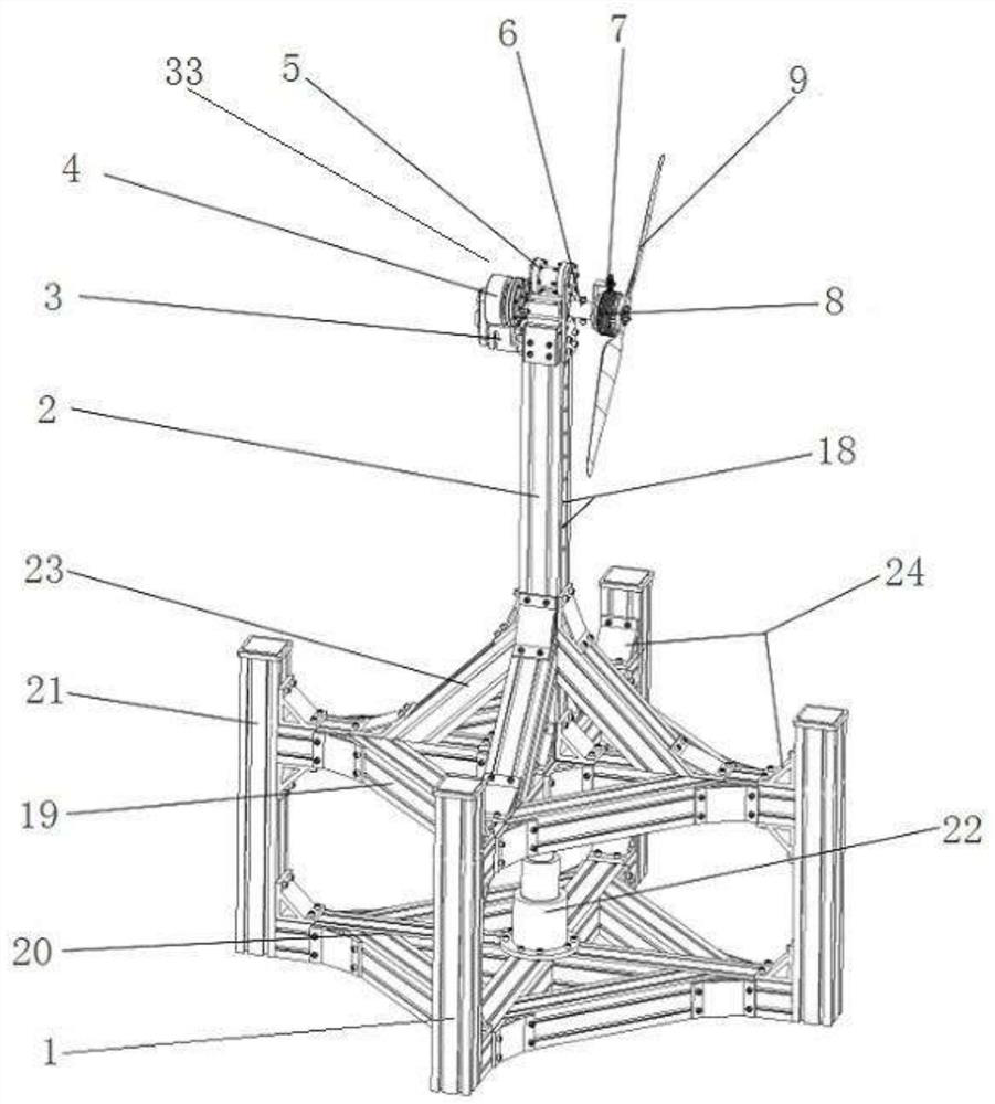
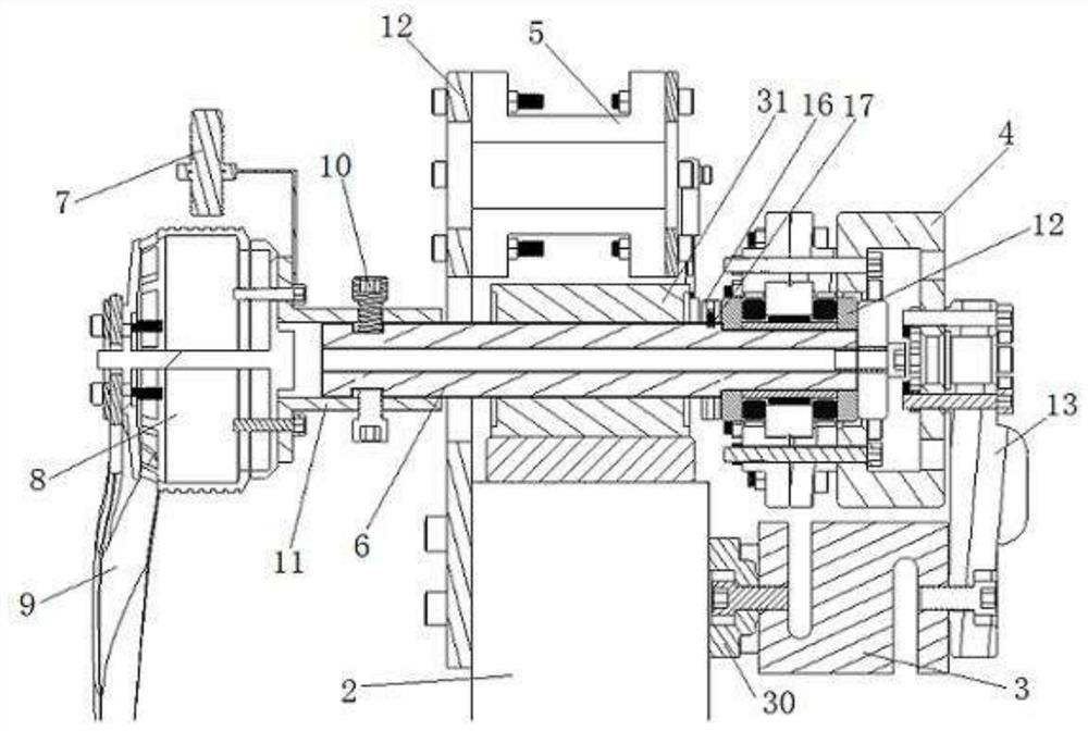
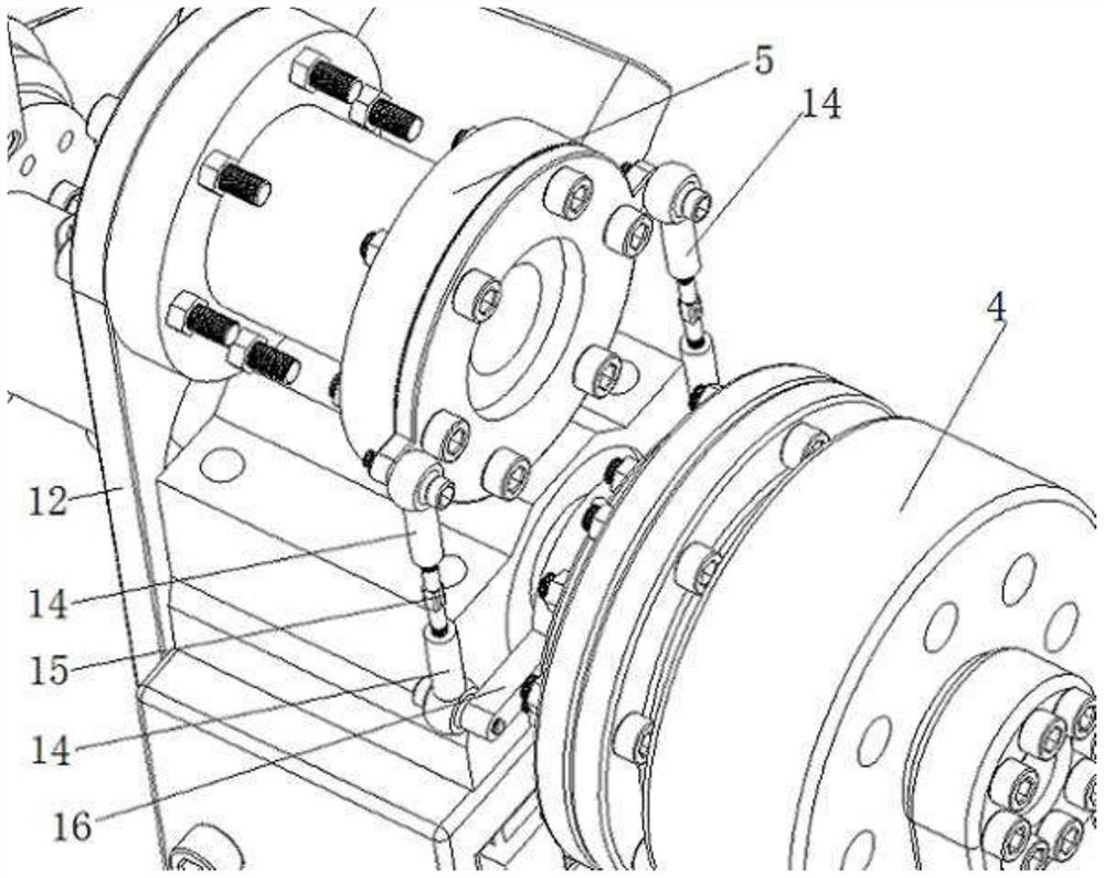
[0018] Such as figure 1 , the supporting seat 1 plays the role of stabilizing the whole test bench, and the central position of the measuring seat can be reinforced and heightened according to the test environment, and the center of rotation of the blade 9 on the test bench can be adjusted to the proper position of the wind tunnel air outlet. The support base 1 includes an upper support base 19, a lower support base 20, an aluminum profile pole 21, an electric telescopic rod 22 and a diagonal strut 23, the lower support base 20 is fixedly connected with the vertical pole 21, and there is a right-angle connector 24 at the joint. The center of the lower support base 201 has an electrically controlled telescopic rod 22, and the upper support base 19 can be controlled to move up and down along the guide rail on the vertical rod 21 by the electrically controlled telescopic rod 22. Fixed connection, there is a sound pressure measurement unit 18 on the side of the support rod 2 close...


PUM


Abstract

The invention discloses a rotorcraft blade performance testing platform, which includes a platform body, a power system and a measurement and control system. The platform body includes a support seat, a support rod and a blade testing mechanism, and the blade testing mechanism includes an S-type tensile and compressive force measuring module. , force transmission ring, torque sensor, force transmission spindle, speed sensor and brushless motor, the inorganic brush is connected to the blade to be tested, one end of the force transmission spindle is fixed with a flange through a stop bolt, and the other end has a force transmission ring , the brushless motor is installed on the flange, the force transmission ring is connected with the force transmission main shaft through the rolling bearing, the force transmission ring is connected with the S-type tensile and compression force measurement module through the dowel rod, and the torque sensor is connected with the fisheye joint bearing and the double The head threaded pull rod is connected with the torque rocker arm, and the torque rocker arm is installed on the power transmission spindle by screws. The length of the support rod and the replaceability of the brushless motor in the present invention enable a wide range of measurable blades, and the S-type tension-compression force measuring module and torque sensor can be replaced to meet different test requirements and accuracy requirements.

Description

technical field [0001] The invention relates to a blade testing device, in particular to a rotorcraft blade performance testing platform. Background technique [0002] At present, rotorcraft have been widely used in aerial photography, plant protection, security and other fields, and the pulling force of the fixed-pitch blades used in them is gradually increasing, and the requirements for the comprehensive performance of the blades are also increasing. Therefore, it is particularly important to test and select the designed blade for tension, power, noise, etc. [0003] At present, the existing blade performance test bench has a six-component balance test bench for testing helicopter rotor blades. This test bench is large in size, low in precision of force measurement, and high in cost, and is not suitable for one-way blades of fixed-pitch rotorcraft. force measurement requirements, and does not have the measurement requirements of blade noise. For the test bench with blade...

Claims


Application Information

Patent Timeline
Patent Type & Authority Patents(China)
IPC IPC(8): B64F5/60
CPCB64F5/60
Inventor 杜思亮曹苏群孙宏佳
Owner HUAIYIN INSTITUTE OF TECHNOLOGY
Learn More