An activated carbon particle preparing device

A technology of activated carbon particles and preparation device, which is applied in inorganic chemistry, non-metallic elements, carbon compounds, etc., can solve the problems of large operation vibration, low output, high noise, etc., and achieve the effect of improving product molding quality

Inactive Publication Date: 2018-12-18
ZHONGYE-CHANGTIAN INT ENG CO LTD
View PDF4 Cites 1 Cited by
  • Summary
  • Abstract
  • Description
  • Claims
  • Application Information

AI Technical Summary

Problems solved by technology

The piston movement driven by the crank mechanism is reciprocating and intermittent, and one reciprocating movement can form a briquette at a time. The output is not very high, and the operation vibration is relatively large, and the noise is relatively large.

Method used


Image

  • An activated carbon particle preparing device
  • An activated carbon particle preparing device
  • An activated carbon particle preparing device

Examples


Embodiment 1

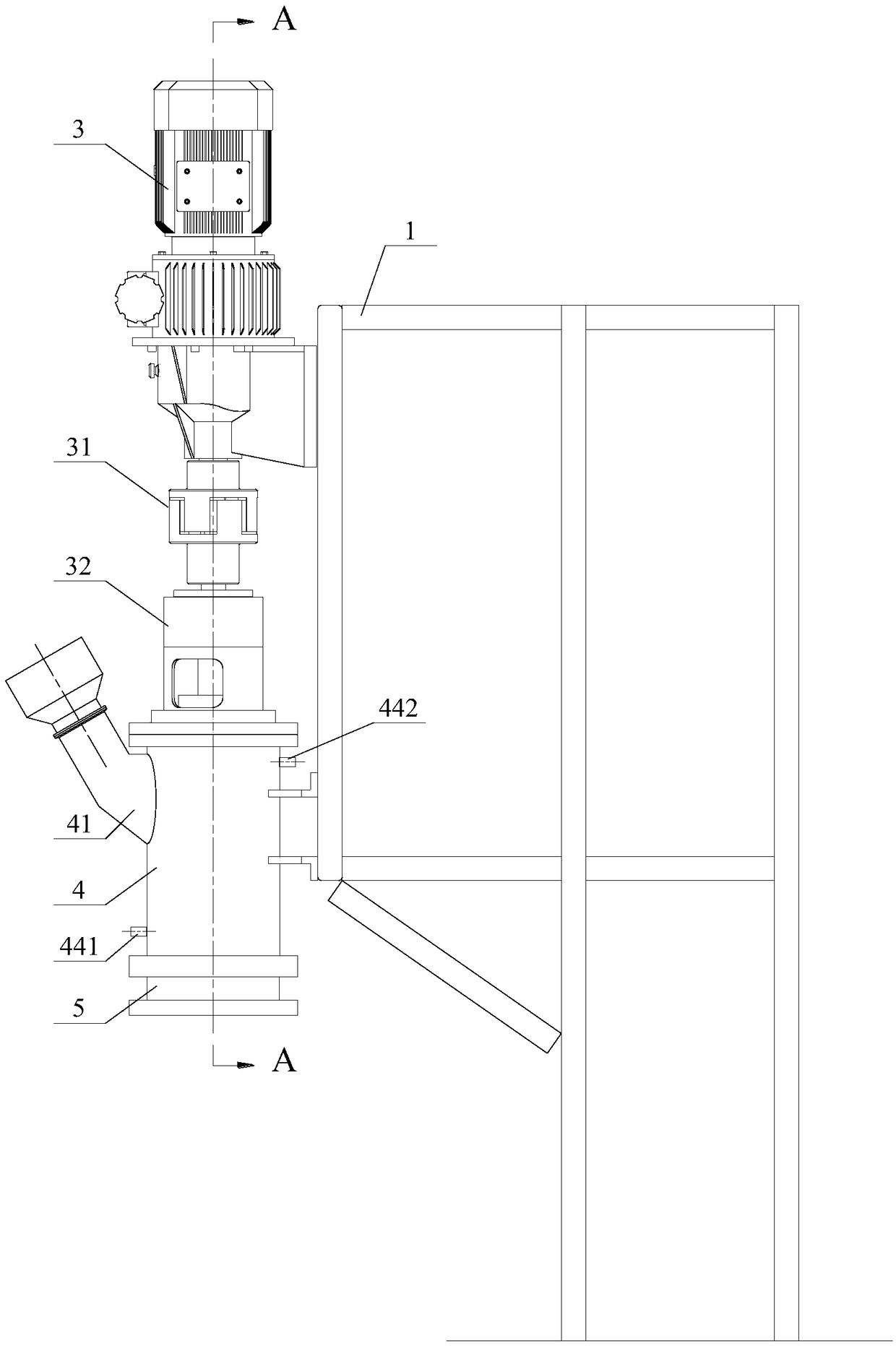
[0034] See figure 1 , which shows a schematic diagram of the overall structure of the device for preparing activated carbon particles according to this embodiment.

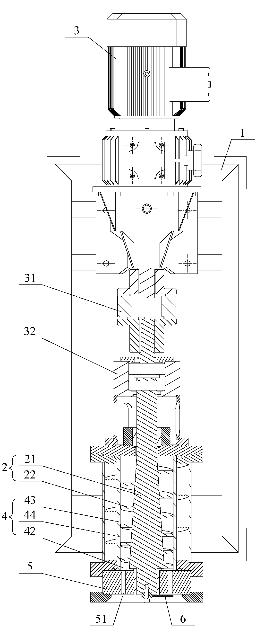
[0035] This activated carbon granule preparation device comprises as the frame 1 that device constitutes bearing support, as figure 1 As shown, the frame 1 is provided with a driving component for driving the extrusion auger 2, preferably a motor 3; its forming cavity 4 has a material cavity 43 and a material inlet 41 and a material outlet 42 connected thereto. Wherein, the extrusion auger 2 is inserted in the molding cavity 4, the rotating shaft 21 of the extrusion auger 2 can be connected with the output end of the motor 3, and the rotating shaft 21 in the molding cavity 4 has a helical blade 22, And it is configured such that along the pushing direction of the material, the extrusion ratio formed in the material chamber 43 tends to gradually increase. Here, "extrusion ratio" refers to the ratio of the density...

Embodiment 2

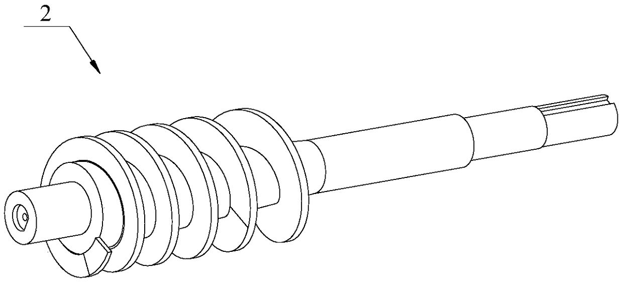
[0046] The difference between this solution and the activated carbon granule preparation device described in Example 1 is that the screw blade 22 of the extrusion auger 2 is a segmented detachable connection structure. See Image 6 , which shows an exploded schematic diagram of the assembly of the extrusion auger. In order to clearly show the difference and connection between this solution and the embodiment, the same functional components in the figure are shown with the same symbols. like Image 6 As shown, the segmented detachable connection structure is specifically configured as follows: the helical blade 22 includes three blade body sleeves arranged in sequence along the length direction of the rotating shaft 21; each blade body sleeve includes a connecting sleeve 221 sleeved on the rotating shaft 21, And the blade body 222 placed on the outer surface of the corresponding connection sleeve 221 .

[0047] Wherein, there is a circumferential limiting pair between the con...

Embodiment 3

[0052] The difference between this solution and the device for preparing activated carbon granules described in Example 1 or Example 2 is that the output die 5 is optimized and improved. See Figure 7 and Figure 8 ,in, Figure 7 It is a schematic diagram of the assembly explosion of the discharge die described in this scheme, Figure 8 for Figure 7 A cross-sectional view of the discharge die shown in . In order to clearly show the differences and connections between this solution and the embodiments, the same functional components in the figure are shown with the same symbols.

[0053] As shown in the figure, the discharge die 5 includes a substrate 52 and a plurality of wear-resistant sleeves 53, and the substrate 52 is provided with a plurality of insertion holes 521. Obviously, the arrangement of the insertion holes 521 corresponds to that of the die holes 51. quantity and arrangement. Each wear-resistant sleeve 53 is inserted into the corresponding insertion hole 5...


PUM


Abstract

An activated carbon particle preparing device is disclosed. The device includes a rack and includes a drive component, a molding cavity, an extruding spiral conveyor, a discharging molding die and a cutter which are disposed on the rack. The molding cavity has a material cavity and a material inlet communicating with the material cavity and a material outlet communicating with the material cavity.The extruding spiral conveyor is inserted and connected into the molding cavity. The rotating shaft of the extruding spiral conveyor is in transmission connection with an output end of the drive component, and the rotating shaft in the molding cavity is provided with a spiral blade. The extruding spiral conveyor is configured in a manner that the extrusion ratio in the material chamber graduallyincreases along the material pushing direction. The discharging molding die is at the material outlet of the molding cavity and is provided with a plurality of die holes communicating with the moldingcavity. The cutter is outside the discharging molding die, and is in transmission connection with the rotating shaft of the extruding spiral conveyor so that the cutter is driven by the rotating shaft to cut off a molded material extruded from the die holes. Through the scheme, yield increasing and vibration noise control for a granulation step can be achieved effectively.

Description

technical field [0001] The invention relates to the technical field of metallurgy and environmental protection, in particular to an activated carbon particle preparation device. Background technique [0002] As we all know, in the field of air pollution control, the desulfurization and denitrification activated carbon (that is, large particle activated carbon) process has an outstanding purification effect on flue gas, especially in the purification of flue gas in the iron and steel industry. , Activated carbon can be recycled and other characteristics, will be widely used. At present, the activated carbon industry for flue gas purification is developing rapidly, and the demand for activated carbon continues to grow. [0003] In the prior art, the activated carbon preparation process is mainly carried out in several stages. First, coal powder with a certain particle size is made by crushing and grinding the raw coal; then, after adding a certain proportion of binder and wa...

Claims


Application Information

Patent Timeline
Patent Type & Authority Applications(China)
IPC IPC(8): C01B32/384C01B32/39
CPCC01B32/384C01B32/39
Inventor 戴波刘克俭魏进超李小龙
Owner ZHONGYE-CHANGTIAN INT ENG CO LTD
Why Eureka
Try Eureka