Frozen wall enclosure structure in portal ring beam construction and construction method thereof

A technology of enclosure structure and freezing wall, which is used in earth-moving drilling, wellbore lining, tunnel lining, etc., can solve the problems of uneven reinforcement, large dispersion of reinforcement, poor excavation safety, etc., and achieves a large and uniform freezing range. Good sex, low difficulty effect

Pending Publication Date: 2018-12-18
BCEG CIVIL ENG
View PDF10 Cites 3 Cited by
  • Summary
  • Abstract
  • Description
  • Claims
  • Application Information

AI Technical Summary

Problems solved by technology

[0006] The technical problem to be solved is: the sealed connection structure between the shield tunnel and the station often has the phenomenon of sand and water gushing from the back of the segment. The existing grouting solution has large reinforcement discreteness, uneven reinforcement, and poor effect. Later excavation safety is relatively poor

Method used


Image

  • Frozen wall enclosure structure in portal ring beam construction and construction method thereof
  • Frozen wall enclosure structure in portal ring beam construction and construction method thereof
  • Frozen wall enclosure structure in portal ring beam construction and construction method thereof

Examples


Embodiment Construction

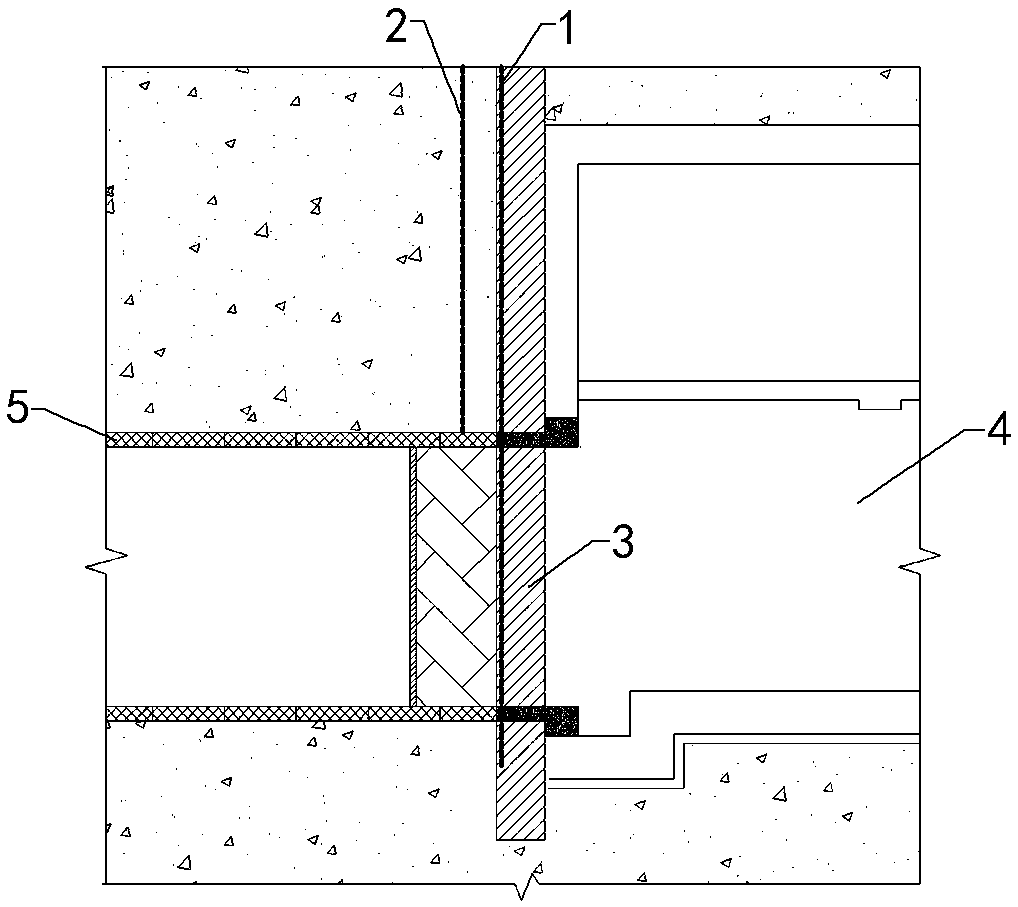
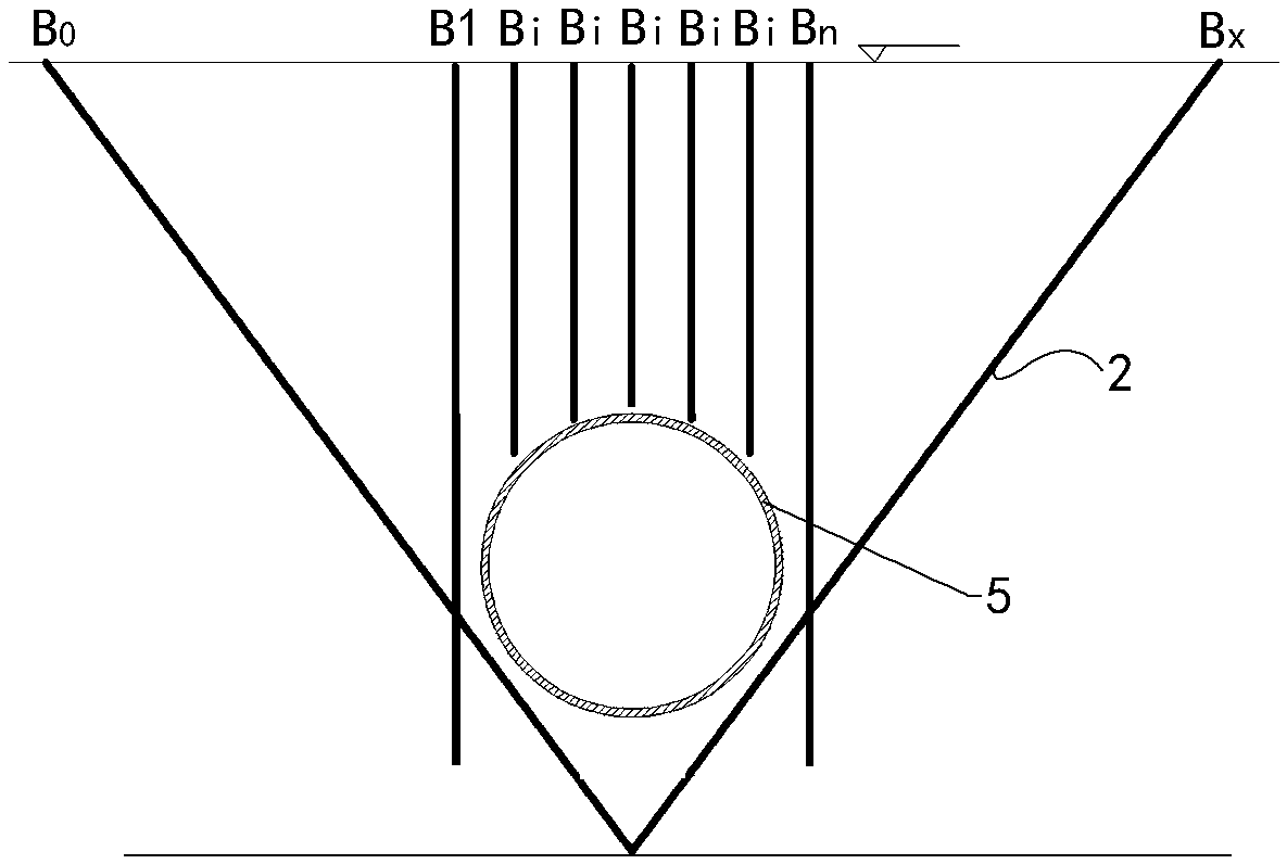
[0043] Such as Figure 1 to Figure 5 As shown, the frozen wall enclosure structure in the construction of the portal ring beam of the present invention includes the A row of frozen pipes 1 and the B row of frozen pipes 2 arranged at the junction of the station foundation pit 4 and the tunnel segment 5; After the liquid nitrogen and brine are sequentially injected into the freezing pipe 2 of row B, a freezing layer with a thickness not less than 1.5 times the width of the door ring beam will be formed at the junction of the station foundation pit 4 and the tunnel segment 5 and in the strata around the tunnel segment 5. Wall 6 enclosure structure.

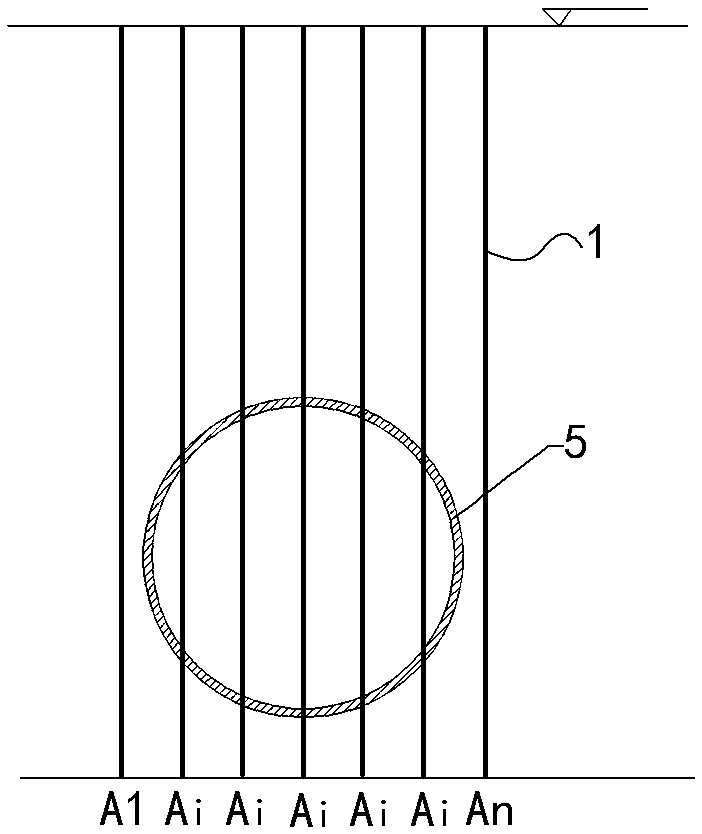
[0044] Such as figure 2 As shown, the A row of frozen pipes 1 is located in the existing occlusal pile 3 of the station foundation pit 4, and is driven vertically from the ground. 1 is a pipe curtain composed of frozen pipes arranged side by side along the longitudinal section perpendicular to the horizontal axis of the tunnel, an...


PUM


Abstract

The invention relates to the technical field of a shield tunnel construction enclosure structure, and discloses a frozen wall enclosure structure in portal ring beam construction and a construction method thereof. The frozen wall enclosure structure comprises A rows of frozen pipes and B rows of frozen pipes. After liquid nitrogen and brine are successively introduced into the A rows of frozen pipes and the B rows of frozen pipes, a frozen wall enclosure structure is formed at a connecting position between a station ground pit and a tunnel duct piece and the stratum at the periphery of the tunnel duct piece. The A rows of frozen pipes are arranged in existing interlocking piles in the station ground pit, and are vertically punched from ground. The A rows of frozen pipes form a pipe curtainwhich is obtained through parallelly arranging the frozen pipes in a longitudinal cross section which is vertical to the horizontal axis of the tunnel. The B rows of frozen pipes and the A rows of frozen pipes are parallelly arranged in the horizontal axis direction of the tunnel. The B rows of frozen pipes are at one side, which is far from the station ground pit, of the A rows of frozen pipes.The B rows of frozen pipes comprise a group of vertically arranged Bc pipes, and a B0 pipe and a Bx pipe at two sides of the Bc pipe. The B0 pipe and the Bx pipe are obliquely and symmetrically arranged. The frozen wall enclosure structure and the construction method thereof have advantages of high soil reinforcing performance and can effectively settle a phenomenon of sand and water surge at a sealed connection part.

Description

technical field [0001] The invention relates to the technical field of shield tunnel construction enclosure structures, in particular to a frozen wall enclosure structure and a construction method thereof in the construction of ring beams at portals. Background technique [0002] In the process of shield tunnel construction, the construction method of tunnel first and then station is more and more widely used. The sealed connection structure between the tunnel completed first and the station constructed later is an important part of tunnel safety. One of the important sources of risk in construction. [0003] The interface between the shield tunnel and the station generally requires construction such as excavation of retaining piles, removal of segments, and excavation of portals. for the whole. During the excavation of the portal, sand and water gushing from the back of the shield segment is more serious; usually, the portal ring beam is constructed after the tunnel is pe...

Claims


Application Information

Patent Timeline
Patent Type & Authority Applications(China)
IPC IPC(8): E21D9/14E21D9/00E21D11/08E21D11/10
CPCE21D9/001E21D9/002E21D9/14E21D11/08E21D11/10
Inventor 阮小赛刘晓毅陈峰刘俊胡文锋周玉林
Owner BCEG CIVIL ENG
Why Eureka
Try Eureka