Eureka AIR delivers breakthrough ideas for toughest innovation challenges, trusted by R&D personnel around the world.

Hydroelectric equipment with anti-blocking function

A technology for power generation equipment and functions, applied in the field of water conservancy power generation equipment with anti-blocking function, can solve the problems of shortened service life of water conservancy power generation equipment, reduced practicability of water conservancy power generation equipment, equipment rust, etc., and achieves strong practicability and reduced congestion. , the effect of prolonging the service life

Active Publication Date: 2018-12-18
国家电投集团广西长洲水电开发有限公司
View PDF7 Cites 4 Cited by
  • Summary
  • Abstract
  • Description
  • Claims
  • Application Information

AI Technical Summary

Problems solved by technology

[0003] When the existing hydroelectric power generation equipment generates electricity, the water flow slows down after passing through the turbine, which causes the sediment carried in the water to accumulate at the bottom of the hydroelectric power generation equipment, forming congestion, which greatly reduces the practicability of the existing hydroelectric power generation equipment, not only In this way, after the existing hydroelectric power generation equipment is used, the moisture in the casing remains, which is likely to cause the equipment to rust, resulting in a greatly shortened service life of the existing hydroelectric power generation equipment

Method used


Image

  • Hydroelectric equipment with anti-blocking function
  • Hydroelectric equipment with anti-blocking function
  • Hydroelectric equipment with anti-blocking function

Examples


Embodiment Construction

[0030] The present invention is described in further detail now in conjunction with accompanying drawing. These drawings are all simplified schematic diagrams, which only illustrate the basic structure of the present invention in a schematic manner, so they only show the configurations related to the present invention.

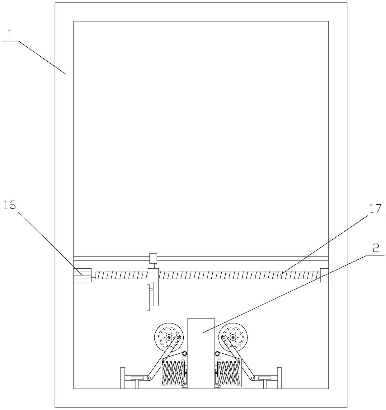
[0031] like figure 1 As shown, a hydroelectric power generation equipment with anti-blocking function includes a casing 1, and the casing 1 is provided with a support column 2, a drying mechanism, two pushing mechanisms and two limiting mechanisms, and the support column 2 is vertically fixed At the bottom of the shell 1, the drying mechanism is located above the support column 2, the drying mechanism is arranged on the inner walls of both sides of the shell 1, and two pushing mechanisms are respectively arranged on both sides of the support column 2, the limiting There is a one-to-one correspondence between the mechanism and the pushing mechanism, and the li...


PUM


Abstract

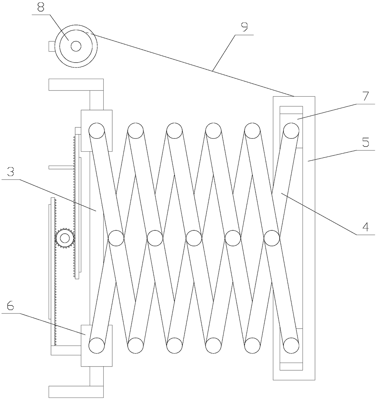
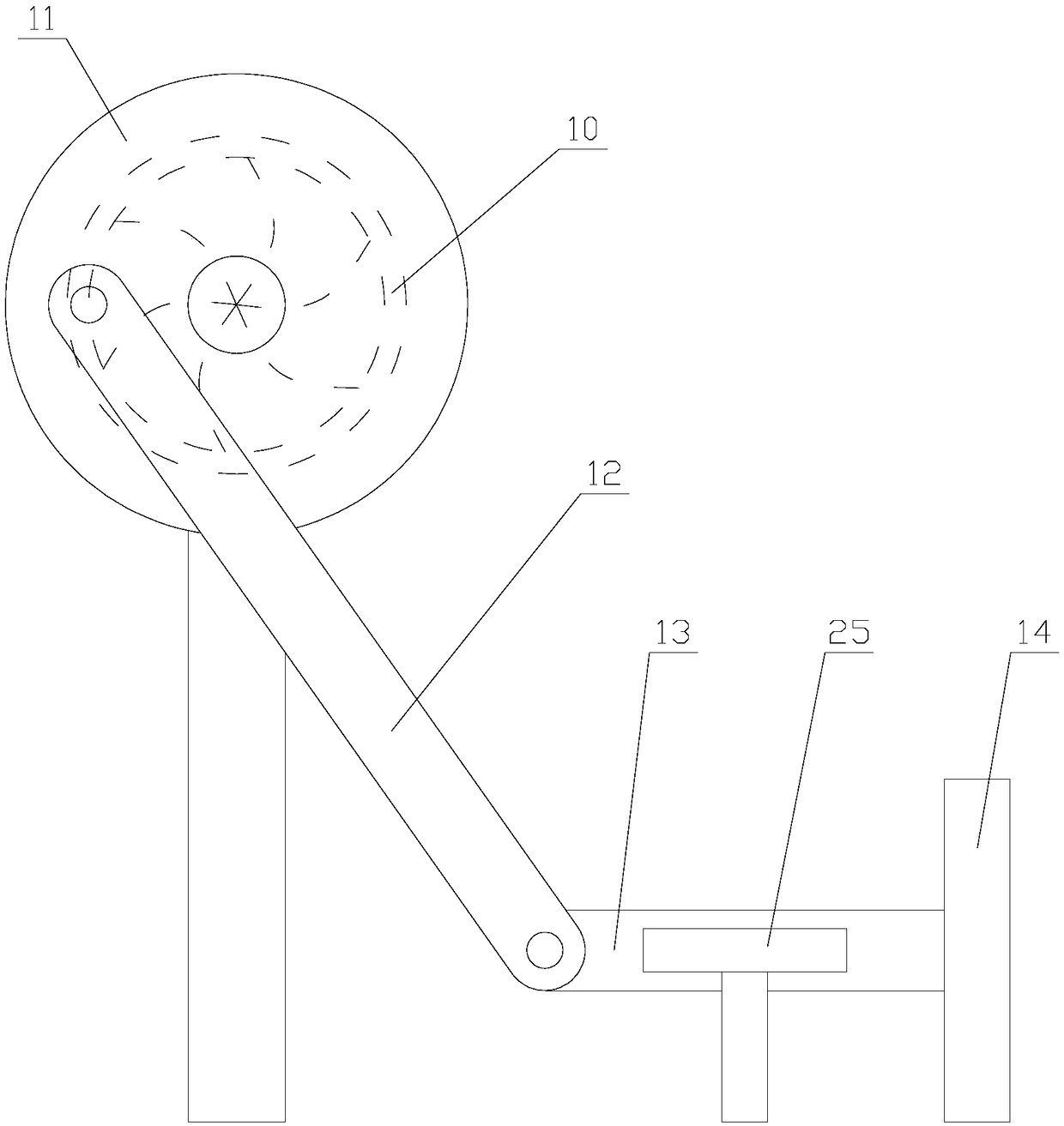
The invention relates to hydroelectric equipment with an anti-blocking function. The hydroelectric equipment comprises a shell, a supporting column, a drying mechanism, two push mechanisms and two limiting mechanisms are arranged in the shell, and each limiting mechanism comprises a telescopic assembly and a limiting assembly. Each telescopic assembly comprises a vertical rod, a driving unit, a telescopic frame, a connecting plate, two cross rods, two sliding blocks and two transmission blocks. Each limiting assembly comprises a cross plate, a rotary shaft, a roller and waterproof cloth. Eachpush mechanism comprises a supporting plate, a water turbine, a rotary disc, a driving rod, a driven rod, a push block and two limiting assemblies. According to the hydroelectric equipment with the anti-blocking function, blocking of the bottom in the shell can be reduced through the limiting mechanisms and the push mechanisms, so that the hydroelectric equipment is higher in practicality; and thebottom in the shell can be dried through the drying mechanism when the hydroelectric equipment is not used, equipment corrosion caused by accumulated water is avoided, and therefore the service lifeof the hydroelectric equipment can be prolonged.

Description

technical field [0001] The invention relates to the field of water conservancy power generation equipment, in particular to a water conservancy power generation device with an anti-blocking function. Background technique [0002] Hydroelectric generating units are also called hydroelectric generating units. The power generation unit formed by the combination of each turbine and the matching generator in the hydropower station is the main power equipment for the hydropower station to produce electric energy. When the water flow quoted by the hydropower station passes through the turbine, the water energy is converted into mechanical energy that drives the machine to rotate; the generator converts the mechanical energy into electrical energy and outputs it. [0003] When the existing hydroelectric power generation equipment generates electricity, the water flow slows down after passing through the turbine, which causes the sediment carried in the water to accumulate at the bo...

Claims


Application Information

Patent Timeline
Patent Type & Authority Applications(China)
IPC IPC(8): F03B13/00F03B11/00F26B21/00
CPCF03B11/00F03B13/00F26B21/004Y02E10/20Y02P70/10
Inventor 曹燕红
Owner 国家电投集团广西长洲水电开发有限公司
Why Eureka
Eureka Blog
Learn More