Turbocharging system with internally-fitted assisting electric motor and cooling system thereof

A technology of turbocharging system and exhaust turbine, which is applied to internal combustion piston engines, mechanical equipment, combustion engines, etc., can solve the problems of slow response, slow response of engines and vehicles, etc.

Inactive Publication Date: 2002-09-04
HONEYWELL INT INC
View PDF2 Cites 0 Cited by
  • Summary
  • Abstract
  • Description
  • Claims
  • Application Information

AI Technical Summary

Problems solved by technology

These fuel limiting devices cause a slower response to throttle opening and cause the engine and car to react sluggishly

Method used


Image

  • Turbocharging system with internally-fitted assisting electric motor and cooling system thereof
  • Turbocharging system with internally-fitted assisting electric motor and cooling system thereof
  • Turbocharging system with internally-fitted assisting electric motor and cooling system thereof

Examples


Embodiment Construction

[0053] Description of the preferred embodiment

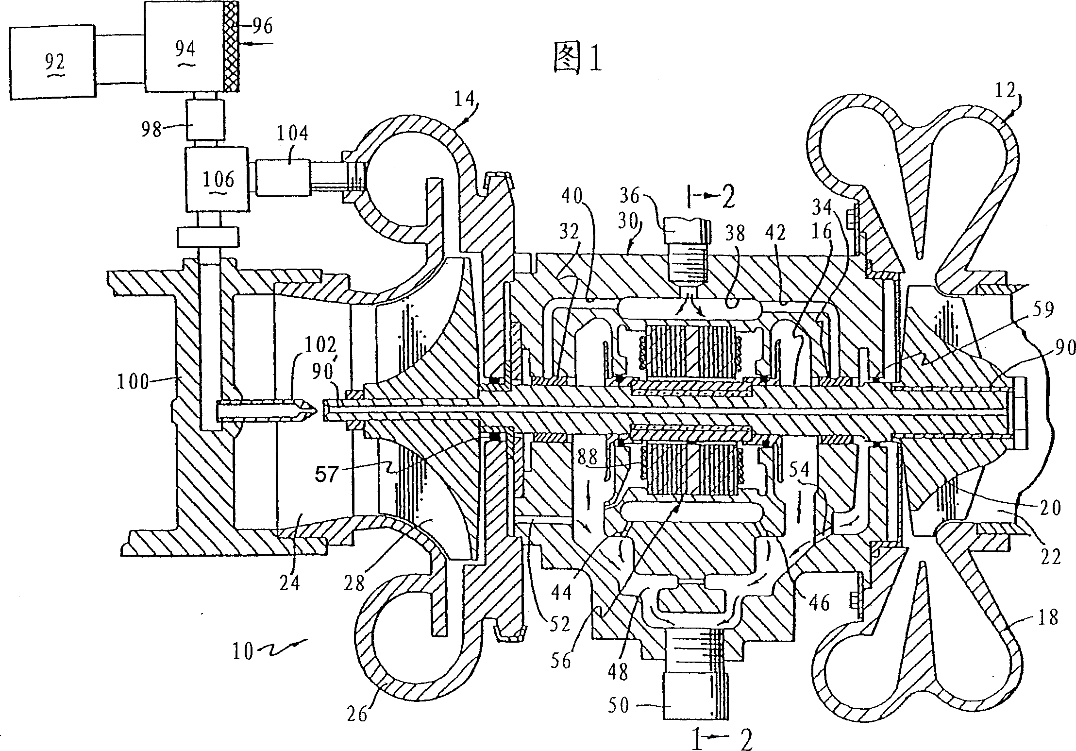
[0054]The turbocharging system of the present invention is indicated generally at 10 in FIG. 1 . The exhaust turbine 12 and charge compressor 14 are most clearly shown in longitudinal section along the centerline of the connecting shaft 16 of the exhaust turbine 12 and charge compressor 14 . The exhaust turbine has an inlet scroll 18 which is connected to receive exhaust gases from an internal combustion engine, such as a diesel engine. The impeller 20 is mounted on the shaft 16 and expands the exhaust gases. Exhaust gas is discharged out of the exhaust pipe 22 . The impeller 20 applies a torque to the shaft 16 and causes the shaft 16 to rotate.

[0055] At the other end of the shaft, an air inlet 24 receives air from the outside after passing through an air filter or similar device which removes a substantial portion of physical contaminants. The intake port 24 is part of a turbocharger that includes a scroll 26 . A compre...


PUM


Abstract

An exhaust gas driven turbine drives a compressor to boost the pressure of an internal combustion engine. A built-in electric motor on the connecting shaft adds power to the turbo shaft, especially at low displacement. Cooling of the electric machine includes circulation of engine oil and may include thermal insulation to confine heat entering from the turbine and air flow through the electric machine to remove heat entering from the turbine.

Description

field of invention [0001] This invention relates to turbochargers driven by exhaust gases from internal combustion engines, and more particularly to the use of a built-in electric motor to increase output at low displacement. Background of the invention [0002] In order to increase the power output of an internal combustion engine of a given displacement capacity, additional air can be supplied by means of compressed air by means of a turbocharger. The additional air allows more fuel to be burned for increased power output. [0003] At very low engine speeds, such as low idle, there isn't enough exhaust energy to drive the turbo fast enough to have a noticeable boost effect. As a result, there's a noticeable lag time between when the engine throttle opens and when the turbocharger turns on fast enough to generate enough boost pressure to eliminate the smoke under acceleration. A fuel control device such as a rack limiter or bellows control is therefore employed to limit t...

Claims


Application Information

Patent Timeline
Patent Type & Authority Patents(China)
IPC IPC(8): F02B37/10F02B39/10F02B39/14F01D5/08F01D15/10F02B37/14F02B37/22F02B37/24F02B39/00
CPCF01D5/085F01D15/10F02B37/025F02B37/10F02B39/005F02B39/10F02B39/14F05D2220/40F02B37/22F02B37/24Y02T10/12
Inventor E·M·哈利米R·P·马鲁弗W·E·伍尔林韦伯
Owner HONEYWELL INT INC
Why Eureka
Try Eureka