Fuel drying device for rural biomass gasification power generation

A drying device and biomass technology, which is applied to the drying of granular materials, drying, drying machines, etc., can solve the problems of unfavorable large-scale production, increase the burden of staff, and reduce drying efficiency, etc., to achieve favorable Large-scale assembly line drying production, compact structure, and the effect of improving drying efficiency

Active Publication Date: 2018-12-18
安徽省建辉生物质能发展有限公司
View PDF8 Cites 4 Cited by
  • Summary
  • Abstract
  • Description
  • Claims
  • Application Information

AI Technical Summary

Problems solved by technology

[0003] When the biomass materials required for the existing biomass gasification power generation are gasified and converted, the solid waste needs to be crushed first, and the solid waste is crushed and decomposed into fine particles, and then the waste particles are dried. Finally, the processed waste particles are input into the gasification furnace for thermal cracking to generate electricity. The current drying device is used to dry the waste particles in the drying room, and most of them use a thermal cycle system for drying, requiring staff to spread the waste particles in layers. Spread it on the material boards of each layer of the drying box, and then input hot air for drying, not only the drying speed is slow, which reduces the drying efficiency, but also increases the burden on the staff, which is not conducive to large-scale production. It brings a lot of trouble to the staff, so we propose a fuel drying device for rural biomass gasification power generation

Method used


Image

  • Fuel drying device for rural biomass gasification power generation
  • Fuel drying device for rural biomass gasification power generation
  • Fuel drying device for rural biomass gasification power generation

Examples


Embodiment Construction

[0032] In order to make the purpose, technical solutions and advantages of the embodiments of the present invention clearer, the technical solutions in the embodiments of the present invention will be clearly and completely described below in conjunction with the drawings in the embodiments of the present invention. Obviously, the described embodiments It is a part of embodiments of the present invention, but not all embodiments. Based on the embodiments of the present invention, all other embodiments obtained by persons of ordinary skill in the art without creative efforts fall within the protection scope of the present invention.

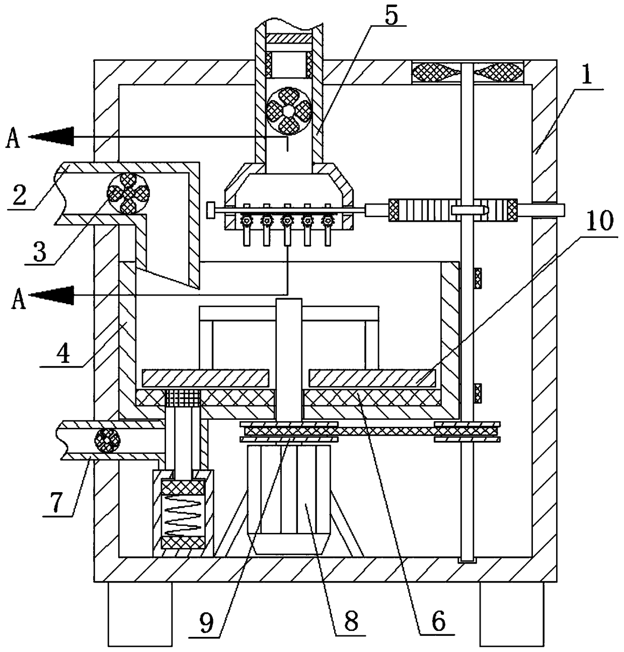
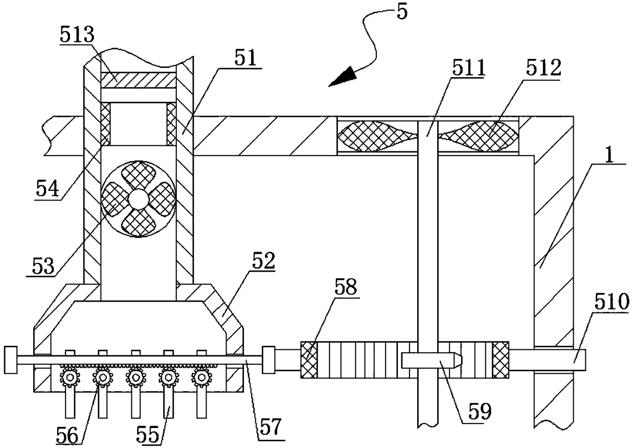
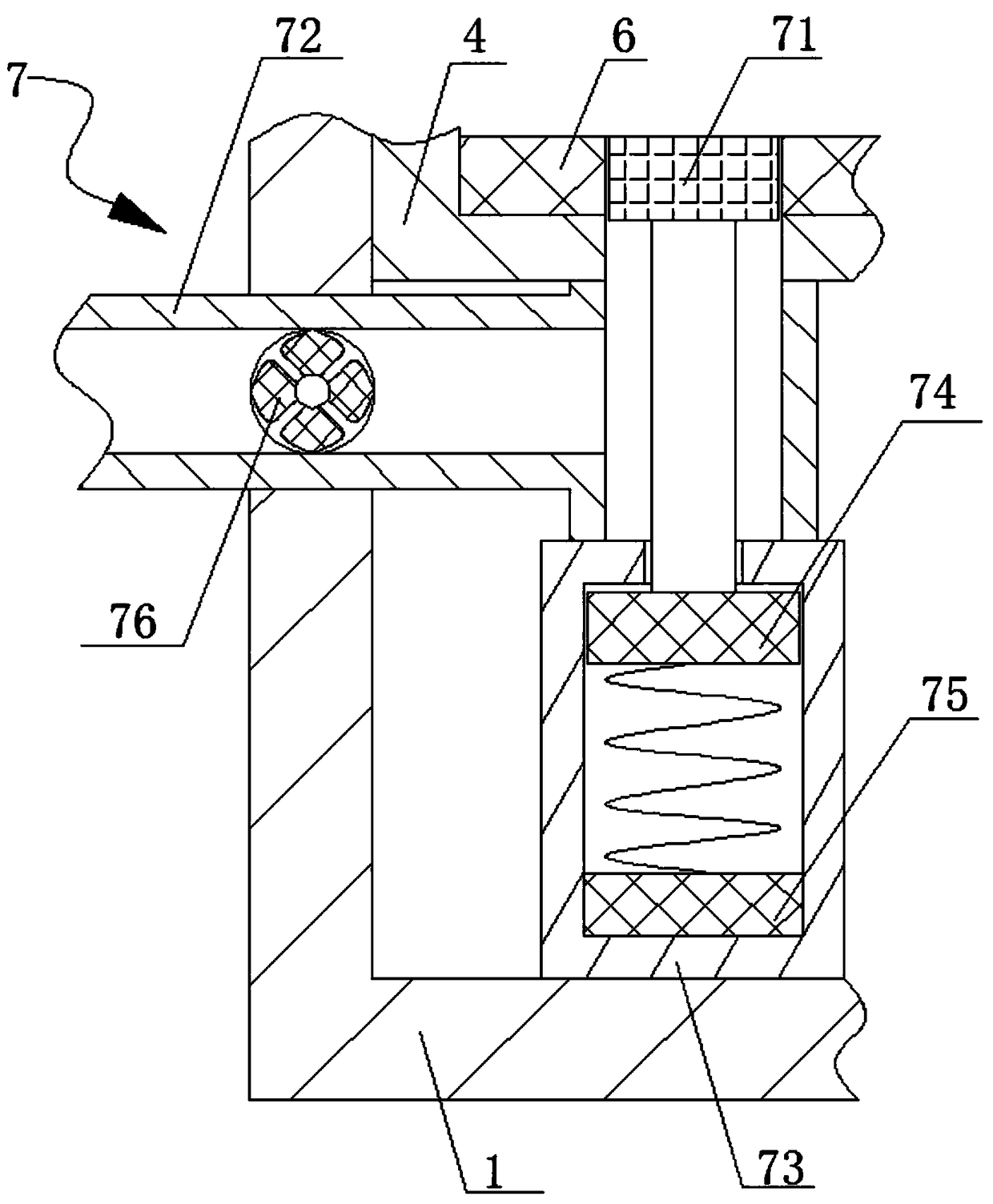
[0033] A fuel drying device for rural biomass gasification power generation, comprising an outer box 1, a feed pipe 2 and a first material pump 3, the lower end of the outer box 1 is fixedly connected with four supporting legs, and one side of the outer box 1 The upper end of the side wall is plugged with a feed pipe 2, the first material pump 3 i...


PUM


Abstract

The invention provides a fuel drying device for rural biomass gasification power generation. The fuel drying device comprises an outer box, a feeding pipe and a first material pump. The lower end of the outer box is fixedly connected with four supporting feet, and the feeding pipe is inserted into the upper end of the side wall of one side of the outer box in a communicating mode. The first material pump is mounted on the feeding pipe. A drying box is fixedly connected to the inner side wall of one side of the outer box, and a hot air circulating device is arranged above the drying box. An electric heating plate is fixedly connected to the inner bottom wall of the drying box, and a plurality of laying stirring plates abut against the upper end of the electric heating plate. According to the fuel drying device, the defects of the prior art are overcome, the design is reasonable, the structure is compact, semi-automatic operation is achieved, waste particles do not need to be laid and sub-packaged, burden of workers is reduced greatly, the drying efficiency is improved, and large-scale assembly line drying production is facilitated.

Description

technical field [0001] The invention relates to the field of biomass gasification power generation equipment, in particular to a fuel drying device for rural biomass gasification power generation. Background technique [0002] Biomass gasification power generation technology is also called biomass power generation system. Simply put, it is to convert various low calorific value solid biomass energy resources (such as agricultural and forestry waste, domestic organic waste, etc.) into biomass gas through gasification. After purification and cooling, it enters the technology of gas generator set for power generation. Seeking a method of using biomass gasification to generate electricity can not only solve the effective use of renewable energy, but also solve the environmental pollution of various organic wastes. Based on the above reasons, biomass gasification power generation technology has been more and more researched and applied, and is becoming more and more perfect. ...

Claims


Application Information

Patent Timeline
Patent Type & Authority Applications(China)
IPC IPC(8): F26B11/00F26B21/00F26B23/06F26B25/04
CPCF26B11/00F26B21/001F26B21/004F26B23/06F26B25/04F26B2200/08
Inventor 倪建辉
Owner 安徽省建辉生物质能发展有限公司
Why Eureka
Try Eureka