Solar cell and solar cell module

A technology of solar cells and components, applied in electrical components, circuits, photovoltaic power generation, etc., can solve the problem of low output power of solar cell components, achieve the effects of reducing current, increasing voltage, and increasing output power

Active Publication Date: 2018-12-18
YINGLI ENERGY CHINA
View PDF6 Cites 2 Cited by
  • Summary
  • Abstract
  • Description
  • Claims
  • Application Information

AI Technical Summary

Problems solved by technology

[0003] In view of this, the embodiment of the present invention provides a solar cell and a solar cell component to solve the problem of low output power of the solar cell component in the prior art

Method used


Image

  • Solar cell and solar cell module
  • Solar cell and solar cell module
  • Solar cell and solar cell module

Examples


Embodiment 1

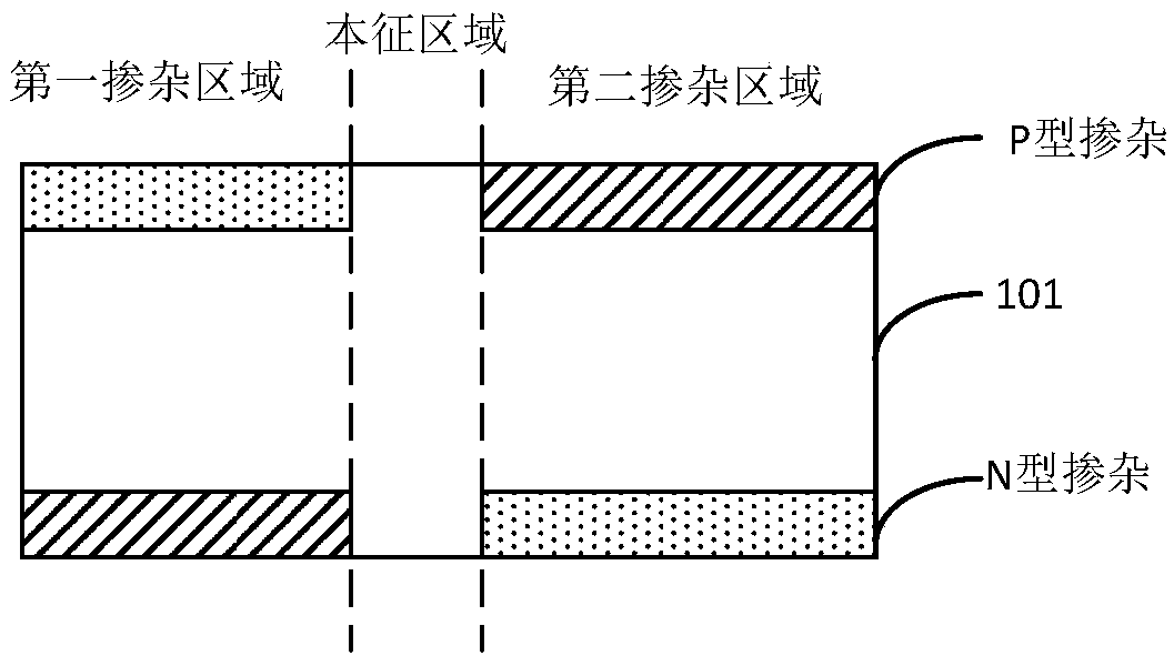
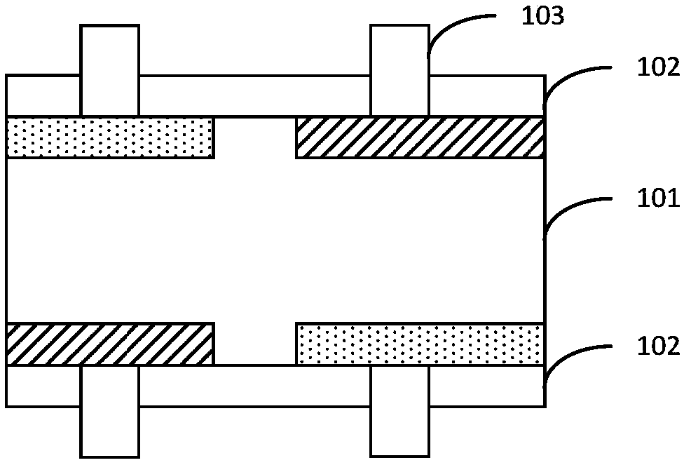
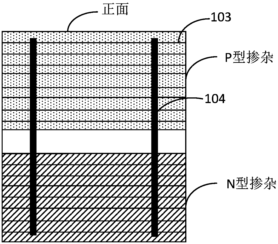
[0027] Please refer to Figure 1 to Figure 4 , the solar cell includes: a substrate 101, the front side of the first doped region in the substrate 101 and the back side of the second doped region are doped with N-type impurities, and the back side of the first doped region in the substrate 101 Both the front surfaces of the doped region and the second doped region are doped with P-type impurities. An intrinsic region is provided between the first doped region and the second doped region in the substrate 101 . A passivation film 102 is provided on the surface of the substrate 101 . Surfaces of the first doped region and the second doped region in the substrate 101 are printed with thin grid lines 103 and main grid lines 104, and the thin grid lines 103 and the main grid lines 104 penetrate through the blunt The chemical film 102 forms an ohmic contact with the substrate 101 . The busbar 104 on the front side of the first doped region in the substrate 101 is connected to the ...

Embodiment 2

[0041] Please refer to Figure 5 and Figure 6 , a solar cell assembly, comprising:

[0042] A plurality of solar cells according to Embodiment 1 of the present invention and a soldering ribbon 200 connecting the solar cells.

[0043] Optionally, the solder 200 is disposed on the busbar 104 on the backlight surface of the solar cell.

[0044] In the embodiment of the present invention, the light-receiving surface of the solar cell is not provided with a soldering ribbon, and the soldering ribbon is provided on the backlight surface of the solar cell, and two adjacent solar cells are connected in series through the soldering ribbon 200, thereby reducing the usage of the soldering ribbon 200 and reducing the Power loss due to ribbon shadowing.

[0045] Optionally, the width of the welding ribbon 200 is 1 mm to 3 mm.

[0046] In the embodiment of the present invention, the width of the welding ribbon 200 is controlled. When the width of the welding ribbon 200 is less than 1 m...


PUM


Abstract

The invention is applicable to the technical field of photovoltaic power generation and provides a solar cell and a solar cell module. The solar cell includes a substrate; the front surface of the first doping region and the back surface of the second doping region in the substrate are doped with N-type impurities, and the back surface of the first doping region and the front surface of the seconddoping region in the substrate are doped with P-type impurities; an intrinsic region is arranged between the first doped region and the second doped region in the substrate. The surface of the substrate is provided with a passivation film; the surfaces of the first doped region and the second doped region in the substrate are printed with a thin gate line and a main gate line, and the thin gate line and the main gate line penetrate the passivation film to form ohmic contact with the substrate; and a main gate line on the front side of the first dope region in the substrate is connected to a main gate line on the front side of the second dope region. The invention can prevent the fragmentation of the solar cell caused by laser scribing and improve the output power of the solar cell module.

Description

technical field [0001] The invention belongs to the technical field of photovoltaic power generation, and in particular relates to a solar cell and a solar cell component. Background technique [0002] Photovoltaic power generation is an important field of new energy development, and improving the output power per unit area of ​​solar cells is the ultimate goal of photovoltaic technology progress. Existing solar cell modules usually cut the solar cells into multiple small cells by laser scribing, and then connect the small cells in series to form battery strings through welding ribbons. However, the electrical performance loss caused by the welding ribbons leads to The output power of the solar cell module decreases. Moreover, the laser scribing process will bring additional damage to the solar cells, resulting in a further reduction in the output power of the solar cell modules. Contents of the invention [0003] In view of this, the embodiment of the present invention ...

Claims


Application Information

Patent Timeline
Patent Type & Authority Applications(China)
IPC IPC(8): H01L31/0352H01L31/05
CPCH01L31/0352H01L31/035272H01L31/0504Y02E10/50
Inventor 王子谦张伟郎芳沈艳娇翟金叶孟庆超张文辉张向前李锋史金超
Owner YINGLI ENERGY CHINA
Why Eureka
Try Eureka