5G dual-band MIMO antenna based on two units

A dual-band antenna, 5G technology, applied in the direction of antenna, antenna coupling, antenna components, etc., can solve the problems of limiting the practicability of communication equipment and the difficulty of taking into account the high gain performance of electromagnetic coupling antennas, so as to overcome the complexity of the unit structure and ensure Independent work performance, overcome the effect of large backward energy radiation

Active Publication Date: 2018-12-18
XIDIAN UNIV +1
View PDF13 Cites 2 Cited by
  • Summary
  • Abstract
  • Description
  • Claims
  • Application Information

AI Technical Summary

Problems solved by technology

[0006] To sum up, with the improvement of communication rate and communication capacity requirements in mobile communication scenarios, although there are many technical solutions that can implement MIMO layout in a smaller volume, these solutions are often difficult to take into account the small electromagnetic coupling between units and The high gain performance of the antenna greatly limits the practicability of communication equipment

Method used


Image

  • 5G dual-band MIMO antenna based on two units
  • 5G dual-band MIMO antenna based on two units
  • 5G dual-band MIMO antenna based on two units

Examples


Embodiment 1

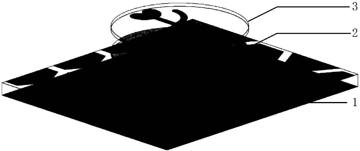
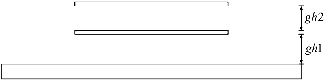
[0036] refer to figure 1 and figure 2 , the present invention includes an artificial magnetic conductor 1, a first dual-frequency antenna 2 directly above the artificial magnetic conductor 1, and a second dual-frequency antenna 3 directly above the first dual-frequency antenna 2; the first dual-frequency antenna 2 and the The distance between the artificial magnetic conductors 1 is gh1, gh1=6mm, the distance between the second dual-frequency antenna 3 and the first dual-frequency antenna 2 is gh2, gh2=5mm; This makes the structure of the whole antenna system more compact, and the existence of the artificial magnetic conductor under the antenna reduces the backward radiation of the antenna and enhances the forward radiation of the antenna unit, which improves the gain of the antenna system.

[0037] refer to image 3 and Figure 4 , the artificial magnetic conductor 1 adopted in the present invention is composed of a magnetic surface 11, a rectangular dielectric substrate 1...

Embodiment 2

[0045] The structure of this embodiment 2 is the same as that of embodiment 1, only the following parameters are adjusted:

[0046] The length lo=7.2mm of the rectangular metal patch, the width wl=1mm, the radius r1=3.3mm of the semicircle in the "heart" shaped metal patch; the radius lh=4.8mm of the quarter arc segment, the width wh=1mm, The radius r2=0.6mm at the end of the arc segment; the length lf=2.5mm and the width wf=2.4mm of the matching metal patch; the thickness T=1mm of the rectangular dielectric substrate 12; the radius R of the circular dielectric substrate 22,32 =14.6mm, thickness t=0.6mm.

Embodiment 3

[0048] The structure of this embodiment 3 is the same as that of embodiment 1, and only the following parameters are adjusted:

[0049] The length lo=8.0mm of the rectangular metal patch, the width wl=2mm, the radius r1=4.3mm of the semicircle in the "heart" shaped metal patch; the radius lh=6.8mm of the quarter arc segment, the width wh=2mm, The end radius of the arc section r2=1.0mm; the length lf=3.1mm and the width wf=3.0mm of the matching patch; the thickness T=3mm of the rectangular dielectric substrate 12; the radius R=16.6 of the circular dielectric substrate 22, 32 mm, thickness t=1.0mm.

[0050] The technical effect of the present invention is further described below in conjunction with simulation result:

[0051] 1. Simulation conditions and content:

[0052] For the described antenna structure of the present invention, simulation experiments are carried out on its performance in the 3.3GHz-3.6GHz and 4.8GHz-5.0GHz frequency bands.

[0053] Based on the commercia...


PUM

PropertyMeasurementUnit
Heightaaaaaaaaaa
Heightaaaaaaaaaa
Lengthaaaaaaaaaa

Abstract

The invention provides a 5G dual-band MIMO antenna based on two units. The 5G dual-band MIMO antenna comprises an artificial magnetic conductor, a first dual-band antenna and a second dual-band antenna with the same structure as the first dual-band antenna and arranged vertically. The first dual-band antenna is composed of a first upper antenna arm, a circular dielectric substrate and a first lower antenna arm. The first upper antenna arm is composed of a first upper low frequency resonant branch and a first upper high frequency resonant branch. The first lower antenna arm has the same structure as the first upper antenna arm and is rotationally symmetrical about the center of the circular dielectric substrate by 180 degrees. At one side of that edge of the circular dielectric plate, a ''heart'' shape metal patch of the first upper low frequency resonant branch is formed, and is connecte with a metal patch of a quarter arc section of the first upper high frequency resonant branch through a rectangular metal patch. The invention has the characteristics of small size, high isolation and high gain, and has good practical value in the mobile communication of indoor base station becauseof the core-shaped metal patch structure, artificial magnetic conductor and polarization orthogonal arrangement mode.

Description

technical field [0001] The invention belongs to the technical field of antennas, and specifically relates to a two-unit 5G dual-frequency MIMO (Multiple-Input Multiple-Output) antenna under a small-sized terminal with high isolation and high gain, which can be used for indoor base station mobile communication. Background technique [0002] MIMO technology refers to the use of multiple transmitting antennas and receiving antennas at the transmitting end and receiving end, so that signals are transmitted and received through multiple antennas at the transmitting end and receiving end, thereby improving communication quality. MIMO technology can take advantage of multipath effects to provide multiplexing gain and space diversity gain for the system, improve the performance of the communication system, and then improve signal stability and channel capacity. Another feature of MIMO technology is that it can fully utilize the spatial degrees of freedom in multipath channels withou...

Claims


Application Information

Patent Timeline
IPC IPC(8): H01Q1/38H01Q1/52H01Q5/10H01Q5/20H01Q5/307H01Q19/02H01Q21/24
CPCH01Q1/38H01Q1/521H01Q5/10H01Q5/20H01Q5/307H01Q19/02H01Q21/24
Inventor 姜文曹先博刘波洪涛龚书喜
Owner XIDIAN UNIV
Why Eureka
Try Eureka