A method for phase shift control of a charging circuit

A technology of charging circuit and phase-shift control, applied in battery circuit devices, charging stations, charging/discharging current/voltage regulation, etc. The size of the output power and other issues

Active Publication Date: 2018-12-18
SHENZHEN VMAX NEW ENERGY CO LTD
View PDF3 Cites 16 Cited by
  • Summary
  • Abstract
  • Description
  • Claims
  • Application Information

AI Technical Summary

Problems solved by technology

The impact of this problem is that the output power of the main road will also affect the output power of the auxiliary road
For example, when the output power of the main circuit is small or no-load (equivalent to that the high-voltage battery at the first DC output terminal is about to be fully charged or has already been fully charged), the main control will issue a small duty cycle, and even enter the intermittent working mode. When the magnetic flux in the transformer is very small, or almost zero, the induced voltage on the winding of the auxiliary circuit may also be zero. will not be able to meet the needs of use

Method used


Image

  • A method for phase shift control of a charging circuit
  • A method for phase shift control of a charging circuit
  • A method for phase shift control of a charging circuit

Examples


Embodiment Construction

[0026] In order to make the object, technical solution and advantages of the present invention more clear, the present invention will be further described in detail below in conjunction with the accompanying drawings and embodiments. It should be understood that the specific embodiments described here are only used to explain the present invention, not to limit the present invention.

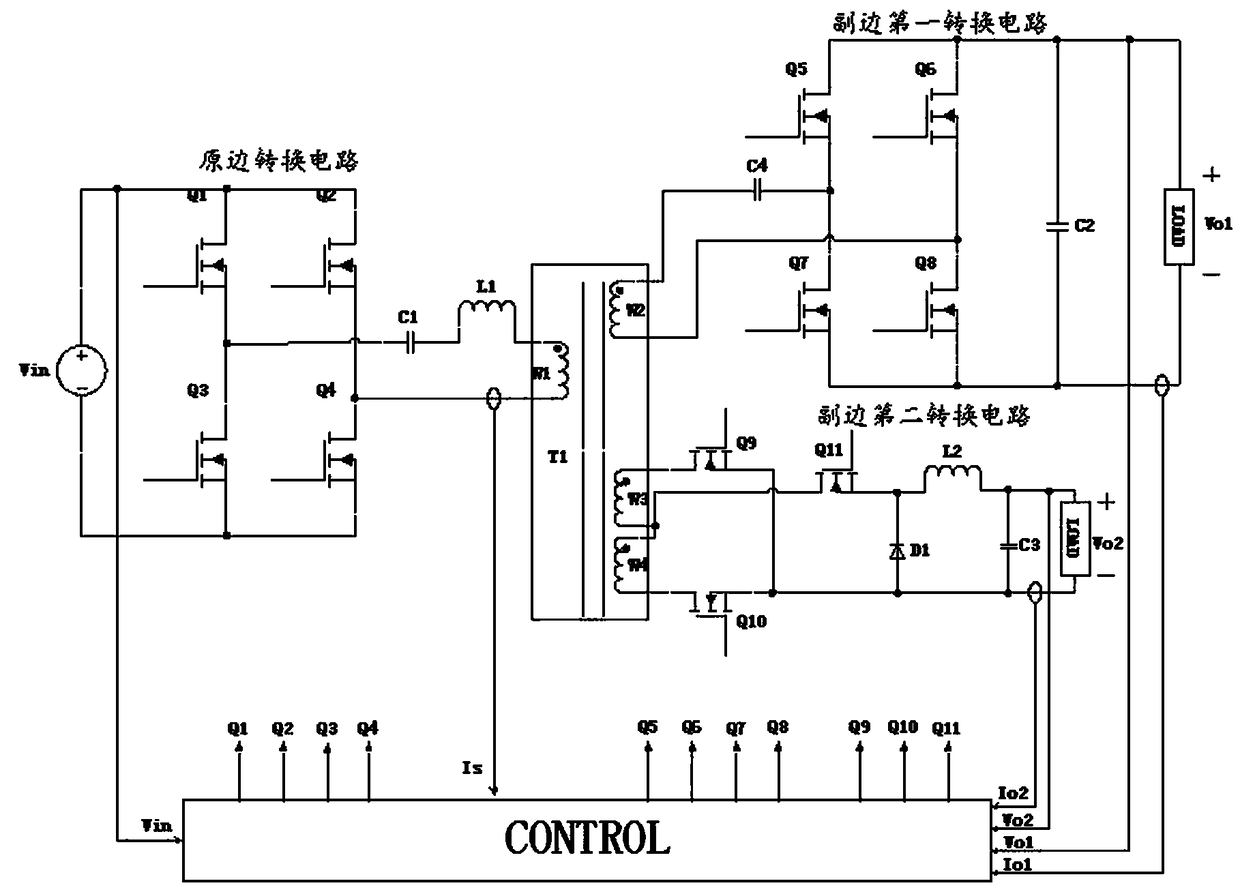
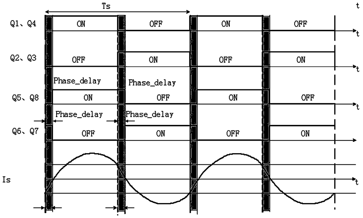
[0027] In the present invention, phase shifting is used to control the output power of the main circuit. No matter how the output power of the main circuit changes, there is always magnetic flux in the transformer. At this time, there is always an induced voltage converted according to the winding pair on the winding of the auxiliary circuit. If a larger output power is required, there will be no problem, which solves the problem of automatic power distribution of the traditional transformer-integrated power supply.

[0028] see figure 1 The topology diagram shown is a phase-shift control metho...


PUM


Abstract

The invention discloses a phase shift control method of a charging circuit, which comprises a primary side conversion circuit, a secondary side first conversion circuit and a secondary side second conversion circuit. The controller has a phase angle difference phi between the on-off waveform of the power switch in the primary side conversion circuit and the on-off waveform of the power switch in the secondary side first conversion circuit; The controller collects the output current (Io1) and the output voltage (Vo1) of the secondary side first conversion circuit through the secondary side first current collector and the secondary side first voltage collector, comparing and calculating the collected output current and output voltage with the preset output current and output voltage, and adjusting the magnitude and positive and negative of the phase angle difference phi according to the comparison result; The magnetic flux in the transformer can be stabilized when the main circuit outputs light load and no load, and the auxiliary circuit can normally absorb electric energy from the transformer and normally supply power to the outside. At the same time, it can conveniently control theconversion direction and the conversion quantity of the electric quantity in each port.

Description

technical field [0001] The invention relates to the technical field of electric vehicle charging, in particular to a phase-shift control method for a charging circuit with three ports. Background technique [0002] With the demand for energy saving and emission reduction, as well as the control of air pollution, new energy vehicles are gradually being promoted and used in the market, among which electric vehicles are the main force of new energy vehicles. The on-board charger of an electric vehicle is an important part of an electric vehicle. The on-board charger generally has an AC input terminal and two DC output terminals. The AC input terminal is connected to the mains network, and the first DC output terminal charges the high-voltage battery. It is equivalent to the output of the main circuit; the second DC output terminal supplies power to the electrical equipment in the car and a small low-voltage battery, which is equivalent to the output of the auxiliary circuit. I...

Claims


Application Information

Patent Timeline
Patent Type & Authority Applications(China)
IPC IPC(8): H02J7/00H02M3/335H02M1/088
CPCH02J7/007H02M1/088H02M3/33576H02M1/009H02M3/285H02M3/33523Y02B70/10Y02T10/70Y02T10/7072Y02T90/14H02M1/0058Y02T10/92B60L53/24B60L2240/527B60L2240/529B60L2260/40B60Y2200/91H02J7/00
Inventor 刘钧冯颖盈姚顺徐金柱
Owner SHENZHEN VMAX NEW ENERGY CO LTD
Why Eureka
Try Eureka