A boost circuit applied to a wireless transmission system

A booster circuit and wireless power transmission technology, applied in control/regulation systems, high-efficiency power electronic conversion, output power conversion devices, etc., can solve the problems of increasing the volume of the secondary side, increasing the volume and cost of the power supply, and achieving low cost, Simple structure and wide application range

Inactive Publication Date: 2018-12-18
SHANGHAI JIAO TONG UNIV
View PDF4 Cites 1 Cited by
  • Summary
  • Abstract
  • Description
  • Claims
  • Application Information

AI Technical Summary

Problems solved by technology

However, simply connecting the boost circuit in series between the power supply and the inverter will significantly increase the size and cost of the power supply
In addition, if further boosting is required on the secondary side, most research is to add a boost boost circuit between the rectifier bridge and the load, but this will also lead to an increase in the volume of the secondary side
At present, there are few studies on the combination of boost network and semi-controlled rectifier boost circuit to achieve boost and soft switching in wireless power transmission systems

Method used


Image

  • A boost circuit applied to a wireless transmission system
  • A boost circuit applied to a wireless transmission system
  • A boost circuit applied to a wireless transmission system

Examples


Embodiment Construction

[0031] The following will clearly and completely describe the technical solutions in the embodiments of the present invention with reference to the accompanying drawings in the embodiments of the present invention. Obviously, the described embodiments are only some, not all, embodiments of the present invention. Based on the embodiments of the present invention, all other embodiments obtained by persons of ordinary skill in the art without making creative efforts belong to the protection scope of the present invention.

[0032] The purpose of the present invention is to provide a boost circuit with a simple structure applied to a wireless power transmission system, so as to boost the input voltage.

[0033] In order to make the above objects, features and advantages of the present invention more comprehensible, the present invention will be further described in detail below in conjunction with the accompanying drawings and specific embodiments.

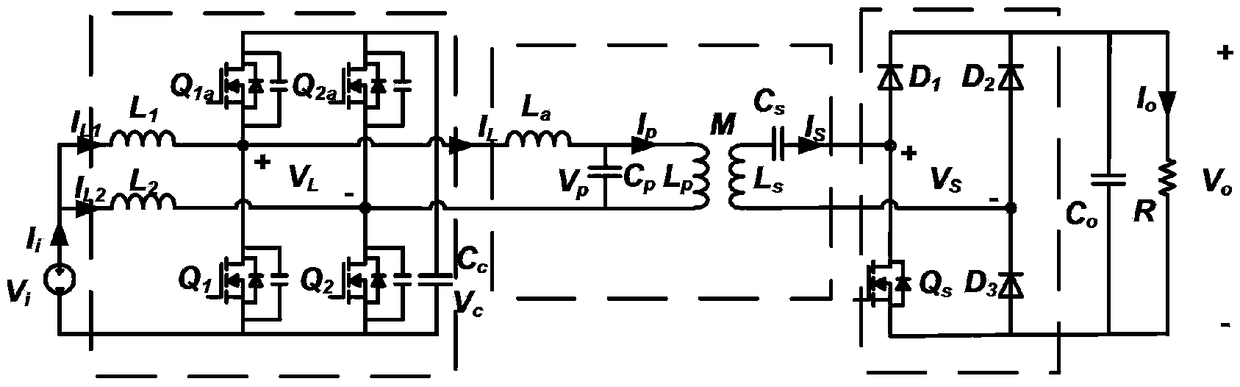
[0034] figure 1 It is a struc...


PUM


Abstract

The invention discloses a boosting circuit applied to a wireless transmission system. The circuit comprises a primary side circuit and a secondary side circuit. The primary side circuit comprises a power supply, a first pre-boosting inductor L1, a second pre-boosting inductor L2, a current inverter, a first electrolytic capacitor Cc, an LCL resonant circuit; The current inverter comprises a firstswitch tube Q1, a second switch tube Q1a, a third switch tube Q2, and a fourth switch tube Q2a. The secondary side circuit includes a series resonant circuit, a first diode D1, a second diode D2, a third diode D3, a fifth switching tube Qs, a second electrolytic capacitor Co, and a load. In the invention, a pre-boosting inductor is arranged on the primary side for supplying the current to the current inverter due to the soft switching required by the switching transistor, so that the conventional full-bridge inverter in the prior art does not need the equivalent load to be inductive so as to realize the soft switching.

Description

technical field [0001] The invention relates to the field of wireless power transmission, in particular to a booster circuit applied to a wireless power transmission system. Background technique [0002] Wireless power transmission system is an important part of the field of power electronics. At present, the research on wireless power transmission system is very extensive. In order to optimize the wireless power transmission system, researchers add more network topologies to the traditional compensation resonance method to improve the system. Efficiency, power and other performance. Among them, there is an LCL resonant network, which is composed of a resonant capacitor connected in parallel with a transmitting coil and then connected in series with a resonant inductor. Since the current on the transmitting coil is proportional to the input voltage and inversely proportional to the inductance of the coil, it is not affected by other parameters (such as load), so the LCL top...

Claims


Application Information

Patent Timeline
Patent Type & Authority Applications(China)
IPC IPC(8): H02M3/335
CPCH02M3/33576H02M1/0058Y02B70/10
Inventor 王天风唐厚君杨喜军马殿光
Owner SHANGHAI JIAO TONG UNIV
Why Eureka
Try Eureka