
A sulfur combustion system for generating sulfur dioxide

A sulfur dioxide, combustion system technology, applied in inorganic chemistry, sulfur compounds, chemical industry and other directions, can solve the problems of high energy consumption, waste of sulfur heat energy, oxygen-deficient combustion, etc., to improve combustion efficiency, increase residence time, and achieve sufficient combustion. Effect

Active Publication Date: 2020-04-24
宣城市楷昂化工有限公司
View PDF5 Cites 0 Cited by
  • Summary
  • Abstract
  • Description
  • Claims
  • Application Information

AI Technical Summary

Problems solved by technology

[0003] The existing sulfur-burning furnace turns the sulfur into a molten state by heating the sulfur with steam or electric heating, and then injects the sulfur into the closed furnace for combustion through the liquid sulfur pump. The process of melting the solid sulfur into a liquid requires a large amount of energy. Energy, the heat energy generated by sulfur combustion is easily wasted
The existing sulfur burning furnace directly burns granular, flake, and massive sulfur in a semi-closed state. The disadvantages are that sulfur gas is easy to leak and cause environmental pollution. The combustion temperature is low, the efficiency is low, the concentration of sulfur gas is low, and the combustion process is difficult to control.
If it is directly burned in a closed state, it is prone to lack of oxygen and incomplete combustion. In severe cases, sublimated sulfur will block the pipeline.

Method used


Image

  • A sulfur combustion system for generating sulfur dioxide
  • A sulfur combustion system for generating sulfur dioxide

Examples


Embodiment

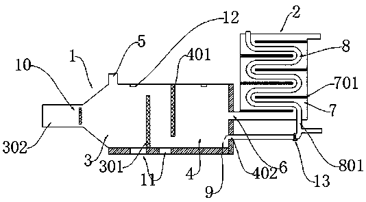
[0026] A sulfur combustion system for generating sulfur dioxide, comprising a combustion furnace 1 and a heat exchange device 2, the combustion furnace 1 includes a connected first combustion chamber 3 and a second combustion chamber 4, the first combustion chamber 3 and the second combustion chamber The top of the chamber 4 is provided with an ignition device 12, the bottom of the first combustion chamber 3 is provided with a first filter plate 301, the top of the second combustion chamber 4 is provided with a second filter plate 401, the first combustion chamber 3 It is isolated from the second combustion chamber 4 by the second filter plate 401, the height of the first filter plate 301 and the second filter plate 401 is 3 / 4~4 / 5 of the furnace height, the first filter plate 301 and the second filter plate The plates 401 all adopt a screen structure, and the side wall of the first combustion chamber 3 opposite to the first filter plate 301 is provided with a primary air inlet ...


PUM


Abstract

The invention relates to the field of chemical technology equipment, in particular to a sulfur burning system for producing sulfur dioxide. The system comprises a combustion furnace and a heat exchange device, wherein the combustion furnace comprises a first combustion chamber and a second combustion chamber which are communicated with each other; a first filtering plate is arranged at the bottomof the first combustion chamber; a second filtering plate is arranged at the top of the second combustion chamber; a primary gas inlet is formed in a side wall on one side, opposite to the first filtering plate, of the first combustion chamber; a material inlet is formed in the top of the first combustion chamber; a gas outlet is formed in a side wall on one side, opposite to the second filteringplate, of the second combustion chamber; a secondary gas inlet is formed in the lower part of the gas outlet; the heat exchange device is connected with the gas outlet. The system has the advantages that sulfur is sufficiently burnt to obtain sulfur dioxide gas with higher concentration, the heat energy of sulfur dioxide is effectively utilized, and energy is saved.

Description

technical field [0001] The invention relates to the field of chemical technology equipment, in particular to a sulfur combustion system for generating sulfur dioxide. Background technique [0002] In the production process of sodium metabisulfite, sulfur dioxide needs to be burned to produce sulfur dioxide. Sulfur dioxide is a colorless gas with a strong pungent smell. It can be felt at 1 ppm in the air. The density of sulfur dioxide gas is 2.26 times that of air. Leaked sulfur dioxide will deposited in the lower part of the air. [0003] The existing sulfur-burning furnace turns the sulfur into a molten state by heating the sulfur with steam or electric heating, and then injects the sulfur into the closed furnace for combustion through the liquid sulfur pump. The process of melting the solid sulfur into a liquid requires a large amount of energy. Energy, heat energy generated by burning sulfur is easily wasted. Existing sulfur furnaces directly burn granular, flaky, and m...

Claims


Application Information

Patent Timeline
Patent Type & Authority Patents(China)
IPC IPC(8): C01B17/54
CPCC01B17/54Y02P20/10
Inventor 许才发
Owner 宣城市楷昂化工有限公司
Learn More