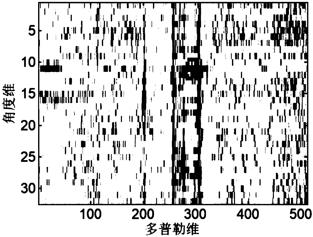
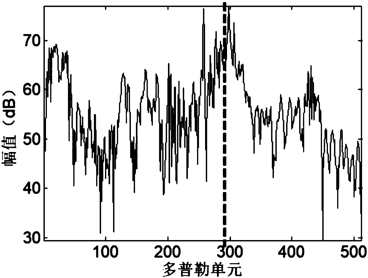
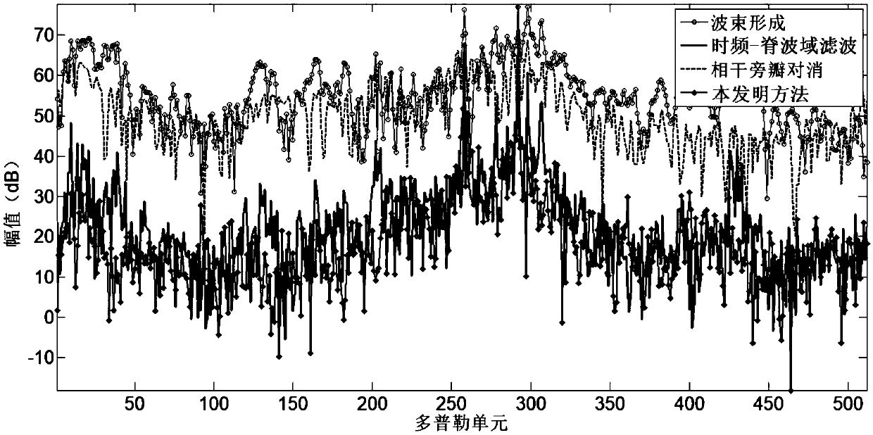
Ionized layer clutter suppression method based on blind source separation and time frequency ridgelet domain filter
A blind source separation and clutter suppression technology, applied in radio wave measurement systems, instruments, etc., can solve problems such as poor clutter suppression effect, achieve good clutter suppression effect, improve signal-to-noise ratio, and good clutter suppression effect of effect
- Summary
- Abstract
- Description
- Claims
- Application Information
AI Technical Summary
Problems solved by technology
Method used
Image
Examples
specific Embodiment approach 1
[0021] Specific implementation mode one: The ionospheric clutter suppression method based on blind source separation and time-frequency ridge domain filtering provided in this implementation mode specifically includes the following steps:
[0022] Step 1, performing source signal separation on the signal received by the radar array antenna through the blind source separation method, and arranging the separated components according to the signal-to-noise ratio from small to large;
[0023] Step 2: Perform beamforming on the signal received by the radar array antenna and the separated components after reordering in the direction of the clutter and the target beam, cancel the beamforming results of the separated components one by one with the beamforming results of the received signal, and select the clutter The cancellation result with the largest noise ratio;
[0024] Step 3: Perform time-frequency-ridge wave domain filtering processing on the canceled result, further improve t...
specific Embodiment approach 2
[0026] Specific embodiment 2: The difference between this embodiment and specific embodiment 1 is that step 1 specifically includes the following steps:
[0027] Step 11. Note that the slow time signal of a certain distance unit received by the radar array antenna with the number of array elements N is X, and the slow time signal of a certain distance unit received by the nth array element for x n , x n ∈ C 1×P , n=1,...,N,C 1×P Represents a real complex number with a dimension of 1×P, where P represents the signal x n The length of , that is, the number of slow-time signal sampling points; then X∈C N×P , C N×P Represents a real complex number whose dimension is N×P; (·) T is the matrix transposition operator; the mth source signal is denoted as s m ,s m ∈ C 1×P , then the set of source signals is S∈C M×P , m=1,...,M, M is the number of source signals, each source signal is independent of each other and comes from different directions, s m from theta m directio...
specific Embodiment approach 3
[0034] Specific embodiment three: the difference between this embodiment and specific embodiment one or two is that the specific process of calculating the signal-to-noise ratio described in step one or two includes:
[0035] Since the speed of the target does not change much within a certain period of time (especially the speed of the ship target and similar ships is slow, and the change within a fixed time is smaller), so when the target enters the ionospheric clutter area, resulting in the loss of the target, You only need to find the target near the Doppler unit when the target is not lost; for the nth separated component y n Perform Fourier transform to obtain the corresponding Doppler spectrum. The Doppler unit when the target is not lost is recorded as i, and the i-th Doppler unit and the area that is less than E Doppler units away from i are used as the target search area, find the maximum value y of the Doppler unit in the target search area [i-E,i+E] n,target , take...
PUM
 Abstract
Description
Claims
Application Information
 - R&D
- Intellectual Property
- Life Sciences
- Materials
- Tech Scout
- Unparalleled Data Quality
- Higher Quality Content
- 60% Fewer Hallucinations
Browse by: Latest US Patents, China's latest patents, Technical Efficacy Thesaurus, Application Domain, Technology Topic, Popular Technical Reports.
© 2025 PatSnap. All rights reserved.Legal|Privacy policy|Modern Slavery Act Transparency Statement|Sitemap|About US| Contact US: help@patsnap.com


