
Laser polishing equipment and method

A laser polishing and laser beam technology, applied in the field of laser polishing, can solve the problems of poor laser spot size and processing stability

Active Publication Date: 2018-12-25
LASER FUSION RES CENT CHINA ACAD OF ENG PHYSICS
View PDF7 Cites 6 Cited by
  • Summary
  • Abstract
  • Description
  • Claims
  • Application Information

AI Technical Summary

Problems solved by technology

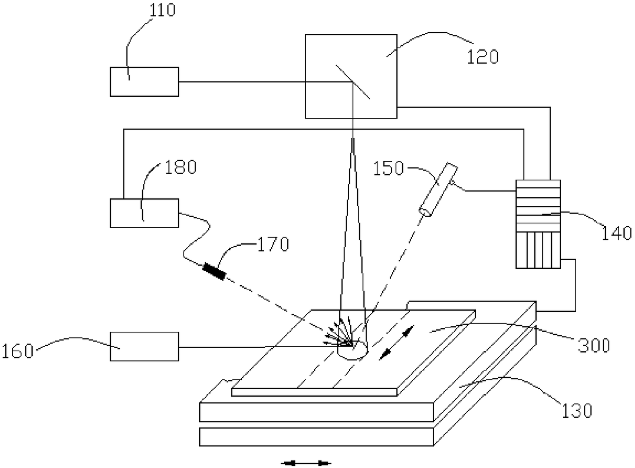
[0004] In view of this, the object of the present invention is to provide a kind of laser polishing equipment and method, to realize the feedback control of the scanning speed and the moving speed of the platform according to the temperature data and the spectral signal, avoid changing the laser power to affect the laser spot size and further Causes poor processing stability

Method used


Image

  • Laser polishing equipment and method
  • Laser polishing equipment and method
  • Laser polishing equipment and method

Examples


Embodiment Construction

[0038] In order to make the purpose, technical solutions and advantages of the embodiments of the present invention clearer, the technical solutions in the embodiments of the present invention will be clearly and completely described below in conjunction with the drawings in the embodiments of the present invention. Obviously, the described embodiments It is a part of embodiments of the present invention, but not all embodiments. The components of the embodiments of the invention generally described and illustrated in the figures herein may be arranged and designed in a variety of different configurations.

[0039] Accordingly, the following detailed description of the embodiments of the invention provided in the accompanying drawings is not intended to limit the scope of the claimed invention, but merely represents selected embodiments of the invention. Based on the embodiments of the present invention, all other embodiments obtained by persons of ordinary skill in the art wi...


PUM

PropertyMeasurementUnit
Wavelengthaaaaaaaaaa

Abstract

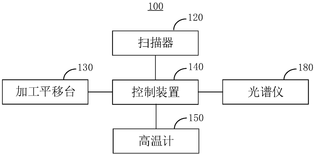
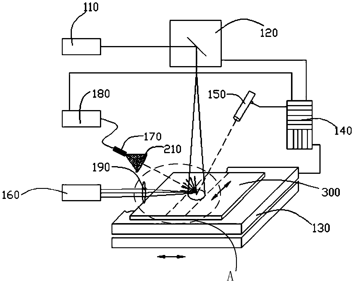
The invention relates to the technical field of laser polishing and in particular relates to laser polishing equipment and method. The equipment comprises a first laser emitter, a pyrometer, a secondlaser emitter, a detector and a spectrograph, wherein the first laser emitter is used for emitting a first laser beam which is projected to a workpiece to be processed on a processing translation platform through a scanner to form a processing zone; the pyrometer is used for acquiring temperature data of the processing zone; the second laser emitter is used for transmitting a second laser beam toa detection focus; the detector is used for detecting a light signal at the detection focus under the action of the second laser beam; the spectrograph is used for acquiring spectrum information according to the light signal; a control device is used for controlling movement speeds of the processing translation platform and scanning speeds of the scanner in a scanning direction according to the spectrum information and the temperature data. Due to the arrangement, scanning speeds and moving speeds of the platform can be fed back and controlled according to the temperature data and the spectruminformation, and the problem that the size of a laser spot is affected as laser power is changed, and poor processing stability is caused, can be avoided.

Description

technical field [0001] The invention relates to the technical field of laser polishing, in particular to a laser polishing device and method. Background technique [0002] Laser polishing technology uses laser beam to scan and process the surface of the workpiece. Through the interaction between the laser and the workpiece to be processed, the excess material on the surface is removed to form a smooth plane. When the laser polishing technology is used to polish the workpiece to be processed, the Under the condition of material evaporation temperature, the higher the laser processing temperature, the better the processing efficiency and effect. [0003] The inventor found through research that when using the existing laser polishing technology to polish the equipment to be processed, the way to control the temperature of the laser treatment is usually to control the laser power output by the laser, but when changing the laser power output by the laser, the laser output by the...

Claims


Application Information

Patent Timeline
IPC IPC(8): B23K26/00B23K26/352B23K26/70
CPCB23K26/00B23K26/352B23K26/70B23K26/702
Inventor 李亚国王度许乔袁志刚刘志超耿锋金会良欧阳升张清华王健
Owner LASER FUSION RES CENT CHINA ACAD OF ENG PHYSICS
Learn More