Eureka AIR delivers breakthrough ideas for toughest innovation challenges, trusted by R&D personnel around the world.

Laser cutting machine splicing bed body and splicing method

A technology of laser cutting machine and bed, used in laser welding equipment, welding equipment, metal processing equipment and other directions, can solve the problem of not exceeding, the laser cutting machine cannot meet the processing requirements, etc., to achieve easy access and increase the overall connection strength , the effect of reducing the error

Pending Publication Date: 2018-12-25
FOSHAN HONGSHI LASER TECH CO LTD
View PDF1 Cites 5 Cited by
  • Summary
  • Abstract
  • Description
  • Claims
  • Application Information

AI Technical Summary

Problems solved by technology

[0004] The existing equipment for processing the body of a laser cutting machine is generally a gantry milling machine. Due to the size limitation of the processed workpiece of the gantry milling machine, in the prior art, the bed length of a single laser cutting machine is no more than 10 meters. The processing range of the laser cutting machine does not exceed. Therefore, when it is necessary to process workpieces with a length of more than 8 meters, the laser cutting machine will not be able to meet the processing requirements. Therefore, it is necessary to improve the machine bed to meet the processing of large-sized workpieces

Method used


Image

  • Laser cutting machine splicing bed body and splicing method
  • Laser cutting machine splicing bed body and splicing method
  • Laser cutting machine splicing bed body and splicing method

Examples


Embodiment 1

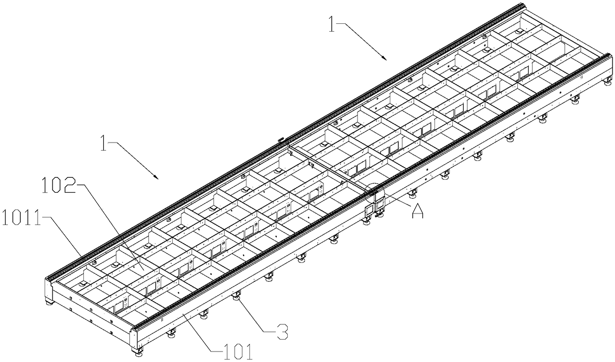
[0060] refer to figure 1 , this embodiment discloses a spliced ​​bed of a laser cutting machine, comprising at least two single bed units 1 and a splicing block 2 connecting adjacent single bed units 1, the single bed unit 1 includes two parallel horizontal The bottom beam 101 and a plurality of longitudinal beams 102 arranged between the two horizontal bottom beams 101, the longitudinal beams 102 and the horizontal bottom beams 101 are connected by welding. 3. Set a plurality of them and evenly distribute them on the bottom of the transverse bottom beam 101 along the length direction of the transverse bottom beam 101.

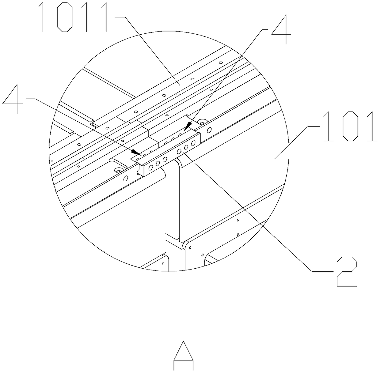
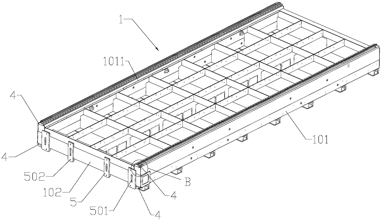
[0061] refer to figure 1 and figure 2 , the top surface of the bed body 1 is provided with a boss surface 1011 for installing the linear guide rail and the rack, the boss is located on the top surface of the two transverse bottom beams 101, the boss surface 1011 can be formed by processing the gantry milling machine, the bed body At least two splicing groo...

Embodiment 2

[0069] Based on Embodiment 1, this embodiment discloses a splicing method for splicing the bed of a laser cutting machine, including:

[0070] S1: Machining bed unit 1

[0071] Process the bed body 1 sequentially through the following processes:

[0072] S1.1: blanking welding;

[0073] S1.2: Annealing the bed body 1;

[0074] S1.3: Perform aging treatment on the bed body 1;

[0075] S1.4: Clean the surface of the bed body 1 and spray anti-rust paint;

[0076] S1.5: Rough machining, semi-finishing, and finishing of the convex table surface 1011 and splicing groove 4 by the gantry milling machine;

[0077] S1.6: Drill pin holes 4011 on the single bed body 1, process threaded holes 4012 on the single bed body with a tap, and drill through holes 502 on the splicing surface;

[0078] S2: Adjust the reference bed body

[0079] Select one bed unit 1 as the reference bed unit, and other bed units 1 as the bed units to be spliced, install the adjusting feet 3 on the bottom of th...


PUM


Abstract

The invention discloses a laser cutting machine splicing bed body and a splicing method. The bed body comprises at least two bed single bodies, the bed single bodies comprise two transverse bottom beams arranged in parallel and a plurality of longitudinal beams connected between the two transverse bottom beams, the top surfaces of the transverse bottom beams are machined for installing a linear guide rail and a convex table surface of a rack, the bottoms of the bed single bodies are provided with adjusting foundations, at least two splicing grooves are respectively formed in the bed single bodies, splicing blocks are arranged between the two adjacent bed single bodies, the splicing blocks are embedded in the splicing grooves of the two bed single bodies, positioning holes and connecting holes are formed in the splicing blocks, when the adjacent two bed single bodies are connected, a pin penetrates through the positioning holes to position the splicing blocks, the splicing blocks are fixed through a screw penetrating through the connecting holes, the two bed single bodies are spliced through the splicing blocks, the structure is simple, and through the adjusting foundation, the splicing bed body meets a higher level degree requirement.

Description

technical field [0001] The invention relates to the field of laser processing equipment, in particular to a splicing bed of a laser cutting machine. Background technique [0002] A laser cutting machine is a machine tool that uses the principle of laser cutting. A laser cutting machine generally includes a bed, a workbench, a beam and a laser cutting head mounted on the beam. The workbench is installed on the bed for clamping to be processed. Workpieces, guide rails and racks are installed on the machine tool to provide guidance for the movement of the beam. The bed of the laser cutting machine is an important part of the laser cutting machine. The strength and flatness of the laser cutting machine have strict requirements. In addition, The size of the bed of the laser cutting machine will determine the size of the workpiece that the laser cutting machine can process. [0003] In the prior art, the Chinese utility model with the notification number CN205817293U discloses a ...

Claims


Application Information

Patent Timeline
IPC IPC(8): B23K26/70B23K26/38B23P15/00
CPCB23K26/38B23K26/702B23P15/00
Inventor 常勇
Owner FOSHAN HONGSHI LASER TECH CO LTD
Why Eureka
Eureka Blog
Learn More