Sole drilling device for production of plastic shoes

A drilling device, plastic technology, applied in the application, footwear, shoe-making machinery and other directions, can solve the problems of deformation, sole carbonization, surface pollution of the drilling device, etc., achieve scientific and reasonable structure, reduce labor intensity, and use safety. handy effect

Active Publication Date: 2018-12-28
浙江杭泉家纺科技有限公司
View PDF5 Cites 5 Cited by
  • Summary
  • Abstract
  • Description
  • Claims
  • Application Information

AI Technical Summary

Problems solved by technology

[0003] The present invention provides a sole drilling device for the production of plastic shoes, which can effectively solve the problem of the traditional drilling device proposed in the above-mentioned background technology because during the drilling process, a large amount of friction will be generated between the drill bit of the drilling device and the sole. Friction will generate a certain amount of heat. Due to the lack of water-cooled components, the heat generated during it cannot be eliminated, resulting in carbonization and deformation of the pores of the sole, which will destroy the integrity of the plastic shoe and reduce the plastic shoe. Due to the lack of rotation adjustment components in the actual drilling process of the existing drilling device, when the guide post drilling device drills the plastic shoe, the position of the plastic shoe cannot be changed, which increases the labor force. The difficulty of adjustment limits the drilling efficiency of the drilling device. In addition, because the existing drilling device lacks waste collection equipment when drilling, the waste and other dirt generated during drilling cannot be cleaned in time. It makes the surface of the drilling device easy to cause pollution, and at the same time increases the labor intensity of subsequent manual cleaning

Method used


Image

  • Sole drilling device for production of plastic shoes
  • Sole drilling device for production of plastic shoes
  • Sole drilling device for production of plastic shoes

Examples


Embodiment

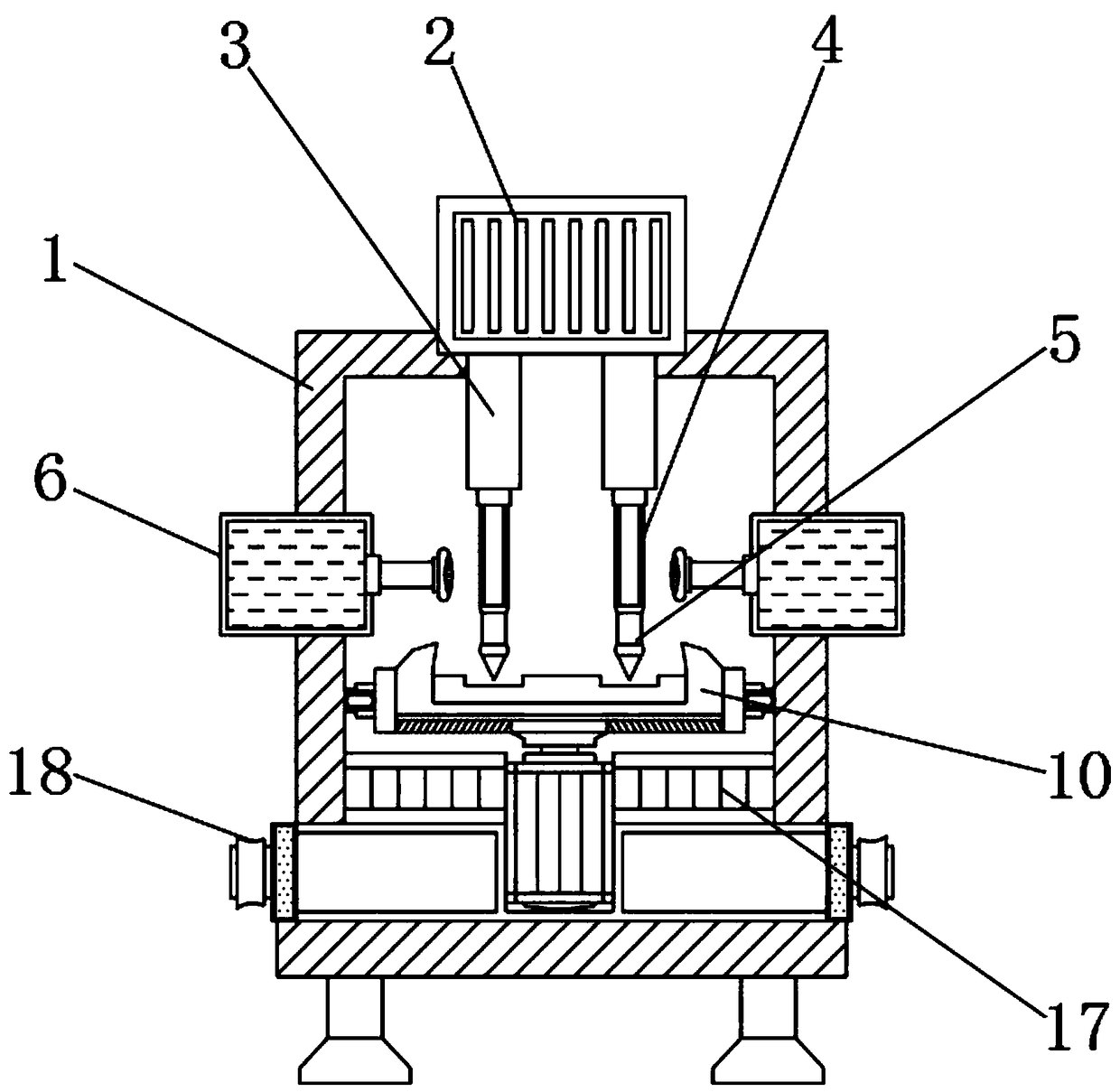
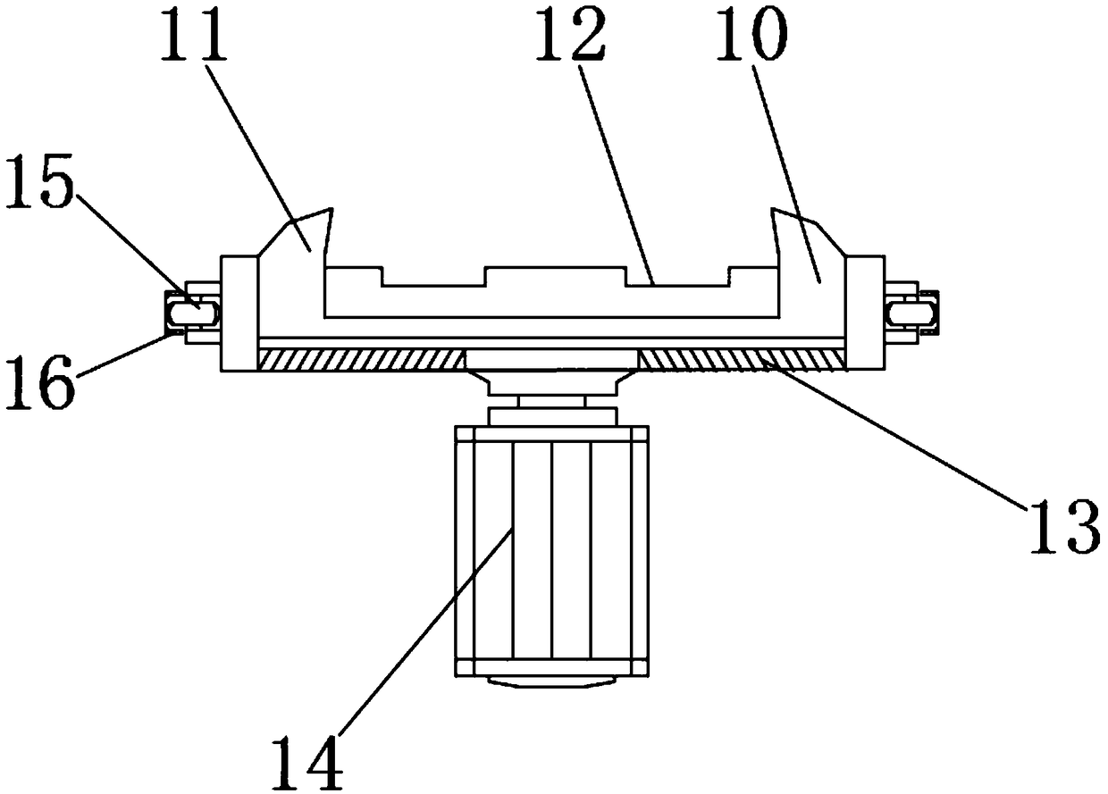
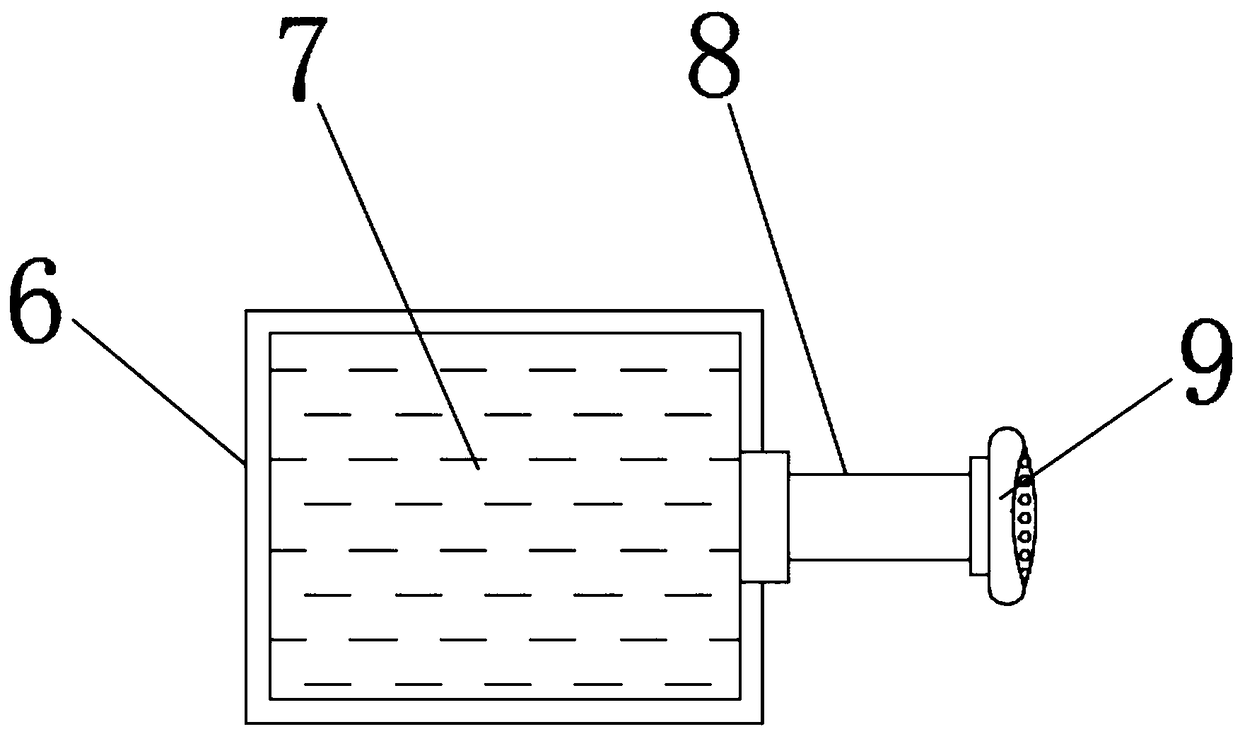
[0022] Example: such as Figure 1-3 As shown, the present invention provides a technical solution, a sole drilling device for plastic shoe production, including a drilling frame 1, a drilling power box 2, a drill arm 3, a grinding roller 4, a drill bit 5, and a water sprayer 6. , Water storage tank 7, water delivery pipe 8, sprinkler head 9, horizontal rotator 10, fixed end angle 11, fitting slot 12, guide groove plate 13, servo motor 14, rotating roller 15, limit plate 16, Leakage chute 17, decontamination device 18, waste collection box 19, filter template 20 and sewage outlet 21. Drilling power box 2 is fixedly installed above the middle of drilling frame 1, in order to make drilling frame 1 in operation The bottom has a higher supporting capacity. The bottom of the drilling frame 1 is fixedly supported with a shock-absorbing base, in order to facilitate the fixed installation between the drilling power box 2 and the drilling frame 1 and to facilitate the drilling of the int...


PUM


Abstract

The invention discloses a sole drilling device for production of plastic shoes. The sole drilling device comprises a water storage tank, a spraying head, a horizontal rotating device, fixed end corners, a waste collecting tank and a filtering template. The inner side of the water storage tank is connected with the spraying head, and the fixed end corners are mounted on the upper portions of the two sides of the horizontal rotating device correspondingly. The filtering template is mounted in the waste collecting tank. The sole drilling device is scientific and reasonable in structure and safe and convenient to use, the spraying head sprays water in the water storage tank to the drilling positions of the drilled plastic shoes through a water conveying pipe, heat generated by drilling of theplastic shoes is eliminated through water cooling, and the phenomenon that the drilling positions of the plastic shoes are carbonized and deform due to the over-high heat is avoided; and a servo motordrives the horizontal rotating device to rotate, thus the drilling positions of the plastic shoes are convenient to adjust, the trouble of manual adjusting is lowered, the drilling efficiency of thedevice is improved, the plastic shoes and the drilling device are more fixedly connected through the fixed end corners, and thus deflecting of the drilling positions during drilling is avoided.

Description

Technical field [0001] The invention relates to the technical field of plastic shoe drilling equipment, in particular to a sole drilling device for plastic shoe production. Background technique [0002] With the current development of society and the continuous progress of plastic processing technology, people’s technological requirements for plastic rubber shoes have also been continuously improved. Plastic shoes are also widely used in various fields of society due to their aspects and environmental protection characteristics. In the actual production process of plastic shoes, the bottom of the plastic shoe needs to be drilled through a drilling device. The traditional drilling device will generate a lot of friction between the drill bit and the sole during the drilling process. , It will generate a certain amount of heat. Due to the lack of water-cooled components, the heat generated during it cannot be eliminated, resulting in carbonization and deformation in the pores of the...

Claims


Application Information

Patent Timeline
Patent Type & Authority Applications(China)
IPC IPC(8): B26F1/16B26D7/01B26D7/00B26D7/18B24B9/20A43D8/00
CPCA43D8/00B24B9/20B26D7/00B26D7/01B26D7/18B26F1/16
Inventor 马成玉
Owner 浙江杭泉家纺科技有限公司
Why Eureka
Try Eureka