Plate-type heat transfer engine

A technology of plate heat exchange and plate heat exchanger, which is applied in the direction of engine components, combustion engines, hot gas variable displacement engine devices, etc., can solve the problems of short fluid channels and inability to apply high-temperature and high-pressure steam heat recycling, and achieve the production process simple effect

Pending Publication Date: 2018-12-28
冯显刚
View PDF0 Cites 4 Cited by
  • Summary
  • Abstract
  • Description
  • Claims
  • Application Information

AI Technical Summary

Problems solved by technology

[0009] The disadvantages of the plate heat exchanger and the spiral plate heat exchanger are that the fluid channel of the plate heat exchanger is short, and although the fluid c

Method used


Image

  • Plate-type heat transfer engine
  • Plate-type heat transfer engine
  • Plate-type heat transfer engine

Examples


Embodiment Construction

[0040] The technical solution of the present invention will be further described below in conjunction with the accompanying drawings.

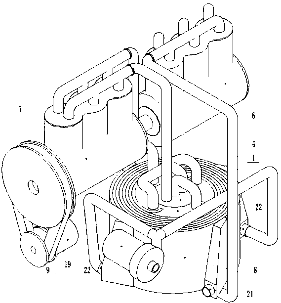
[0041] A plate heat exchange engine includes a heating device 4 , an electric heating device 5 , an internal combustion engine 6 , an external combustion engine 7 , a wound plate heat exchanger 8 , a generator 9 and a water pump 19 .

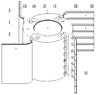
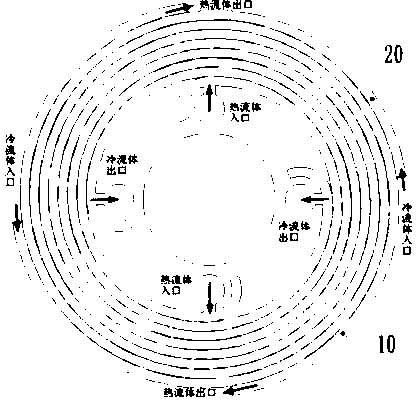
[0042] The wound plate heat exchanger 8, such as figure 2 As shown in the figure, it includes a core body 1, a metal plate 2, a support bar 3, a hot fluid channel 10, a cold fluid channel 20, and a rectangular flow channel 23. The core body 1 is processed with a core body flow channel 11 and a core cavity 12. , fixed groove 13, groove 14, the core flow channel 11 is formed by a round hole with a closed bottom processed on the upper end surface of the core body 1 and a row of round holes communicating with the round hole, and the core cavity 12 is formed on the core body The hole through which the end surface a...


PUM


Abstract

The invention discloses a plate-type heat transfer engine. An internal combustion engine converts the explosive force of fuel combustion gas expansion into mechanical energy, hot gas enters a core cavity of a heat exchanger (a combustion chamber of a boiler) to heat water in a pipeline into high-pressure steam (in an initial stage) to send to an external combustion engine, high-temperature steam discharged by the external combustion turbine and the residual hot gas in the core cavity enter into a hot fluid channel of the heat exchanger separately, and performs convection with the water entering the heat exchanger for heat transfer, when the water flows out of the heat exchanger, the water is heated into high-pressure water vapor and then enters the core cavity to supplement heat loss and increase the temperature, the process is accomplished by a winding plate type heat exchanger with a boiler functional heat transfer rate of over 90%, the heat loss is below 10% of the heat exchanger and other losses, the total loss is calculated at 30%, after the heat of the steam is recycled, the loss is supplemented by the hot gas of the internal combustion engine, 1/0.3=3.3, the heat for the external combustion engine is more than three times that of the internal combustion engine, and the plate-type heat transfer engine is an engine with a perpetual motion effect and the abstract is a combination of the plate-type heat transfer engine. The initial stage is a stage in which the heat of the steam discharged by the external combustion turbine is not recycled.

Description

technical field [0001] The invention relates to a plate heat exchange engine and the field of engines. Background technique [0002] An engine is a machine that can convert other forms of energy into mechanical energy, including internal combustion engines and external combustion engines. [0003] There are many types of internal combustion engines, common gasoline engines and diesel engines. The internal combustion engine uses the explosive force of the rapid expansion of the gas during the chemical reaction of fuel combustion to convert heat energy into mechanical energy, and the hot gas is called "exhaust gas" to be discharged. [0004] The main types of external combustion engines are steam engines and steam turbines. It uses the heat of the chemical reaction of the fuel in the combustion chamber of the boiler to heat the water into high-pressure and high-temperature gas, which is sent to the external combustion engine to convert the heat energy into mechanical energy....

Claims


Application Information

Patent Timeline
IPC IPC(8): F02G1/043F02G1/055F02G5/02F28D9/04
CPCF02G1/043F02G1/055F02G5/02F02G2254/15F02G2254/45F28D9/04Y02E20/30Y02T10/12
Inventor 冯显刚
Owner 冯显刚
Why Eureka
Try Eureka