Low and slow small target tracking method based on polar coordinate system

A low-slow and small target and polar coordinate system technology, which is applied in the field of low-slow and small target tracking based on the polar coordinate system, can solve the problems of target signal concealment, high complexity, and small radar reflection area

Active Publication Date: 2018-12-28
TIANJIN NAVIGATION INSTR RES INST
View PDF7 Cites 23 Cited by
  • Summary
  • Abstract
  • Description
  • Claims
  • Application Information

AI Technical Summary

Problems solved by technology

The radar reflection area of ​​low, slow and small targets is very small, resulting in small and weak target echoes; coupled with its slow flight speed, the Doppler effect caused by it is not obvious, making it difficult for radar to effectively detect targets in the frequency domain; In addition, the flying altitude of low, slow and small targets is low, and the surrounding environment is relatively complex, and the target signal is often easily covered by ground clutter and interference signals.
To sum up, low-slow and small targets have the problems of weak echo, strong clutter influence, and Doppler frequency close to clutter, which makes it very difficult for radar to detect and track them
[0003] In order to solve the problem of radar detection and tracking of low, slow and small targets, some studies consider balloon-borne radar or overhead looking down radar. Compared with ground radar, this type of air-to-ground radar can overcome the influence of earth curvature, topography and complex background environment , but the air-to-ground look-down radar has strong ground clutter reflection echoes in most areas of its range of action, so it must rely on advanced signal processing technology to effectively suppress the clutter. In addition, its complexity is relatively high. The cost of engineering implementation is too high; in terms of radar data processing te

Method used

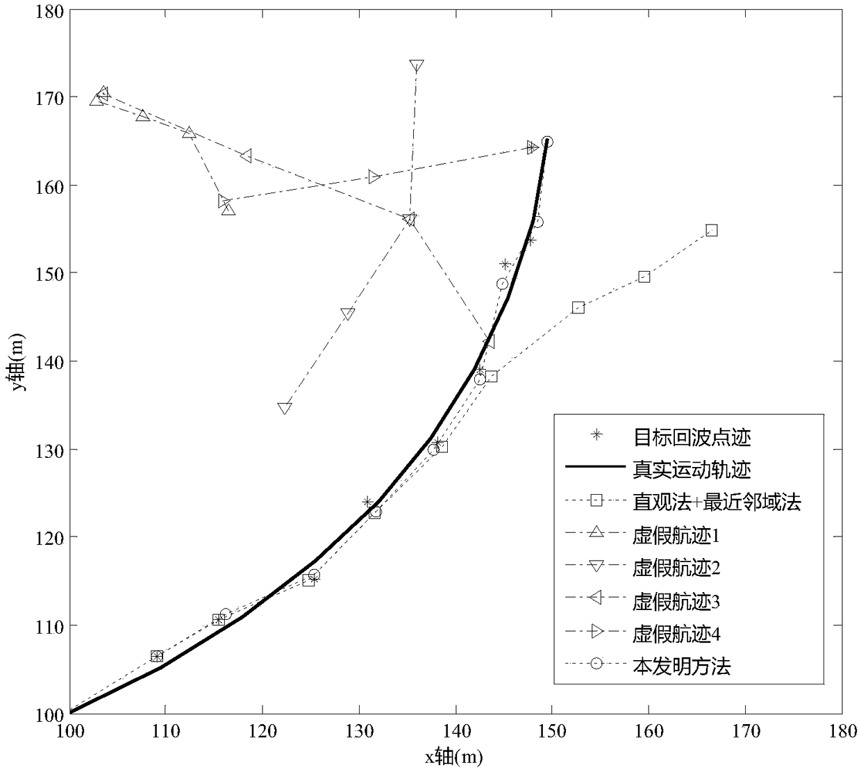
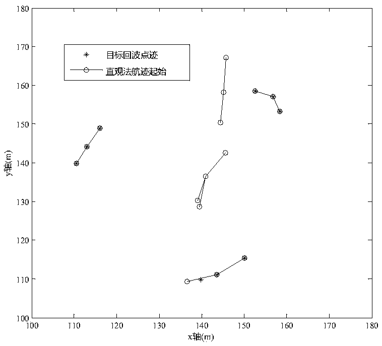
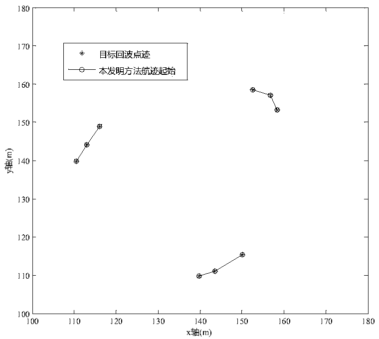

Image

  • Low and slow small target tracking method based on polar coordinate system
  • Low and slow small target tracking method based on polar coordinate system
  • Low and slow small target tracking method based on polar coordinate system

Examples


Example Embodiment

[0074] The following describes the embodiments of the present invention in further detail with reference to the accompanying drawings:

[0075] A method for tracking low, slow and small targets based on a polar coordinate system, including the following steps:

[0076] Step 1. The radar scans the current frame of the measurement point for the first time, and then starts the track start, and uses all the points scanned this time as the track head to establish temporary tracks respectively, that is, all temporary tracks generated are Only one spot

[0077] After the radar system scans each frame, the signal processor will upload the dot trace data packet to the upper computer. The dot trace data packet may contain target dot traces, clutter false alarm points, or no measurement dot traces. The processing cycle of track correlation update is based on the duration of the radar scan frame, that is to say, after the host computer receives the point track data packet in each frame, it will...


PUM


Abstract

The invention relates to a low and slow small target tracking method based on a polar coordinate system. The technical feature is that the method comprises the following steps: step 1. establishing atemporary track by using measurement points scanned by a radar for the first time as track heads respectively; step 2. after the radar scans the measurement point for the second time, determining a relevant wave gate by using speed limit; step 3. after the radar scans the measurement point for the third time, for the temporary track with a trace point number of 2, determining the relevant wave gate through Kalman filtering of the polar coordinate system; step 4. moving the track with a trace point number of 3 in a temporary track set into a reliable track set; step 5. after the radar scans a new measurement point, firstly performing association updating with the reliable track set, and if non-associated measurement points still exist, performing association updating with the temporary track set; and step 6. traversing all tracks, if a certain track is not updated exceeding a certain time, performing track is extinction or extrapolation. By adoption of the low and slow small target tracking method provided by the invention, a decoupling problem and a conversion error are avoided, and meanwhile the calculated amount is reduced.

Description

technical field [0001] The invention belongs to the technical field of radar, and relates to a low-slow and small-target tracking method, in particular to a low-slow and small-target tracking method based on a polar coordinate system. Background technique [0002] The detection and tracking of low, slow and small targets has always been a research hotspot and difficulty in the field of radar technology. Low-slow and small targets (low-altitude and slow-speed small targets) refer to targets with small RCS, slow flight speed, suitable for low-altitude flight, and more flexible and maneuverable implementation of low-altitude and ultra-low-altitude penetration. The radar reflection area of ​​low, slow and small targets is very small, resulting in small and weak target echoes; coupled with its slow flight speed, the Doppler effect caused by it is not obvious, making it difficult for radar to effectively detect targets in the frequency domain; In addition, the flying altitude of ...

Claims


Application Information

Patent Timeline
IPC IPC(8): G01S13/66
CPCG01S13/66
Inventor 张凯丽周喆王宁单彬赵娜王宏房媛媛傅天爽
Owner TIANJIN NAVIGATION INSTR RES INST
Why Eureka
Try Eureka