MOS switch drive circuit for series battery pack battery management system and array thereof

A switch drive circuit and battery management system technology, applied in electronic switches, circuits, secondary batteries, etc., can solve the problems of high chip price, complex structure, and high price, so as to improve system reliability and simplify drive circuit structure , cost reduction effect

Inactive Publication Date: 2019-01-01
付允念
View PDF12 Cites 10 Cited by
  • Summary
  • Abstract
  • Description
  • Claims
  • Application Information

AI Technical Summary

Problems solved by technology

There are some companies in the market that can produce dedicated chips and provide corresponding active equalization related solutions. For example, Texas Instruments has launched a dedicated active equalization chip and supporting solutions. However, due to its market monopoly, the price of the chip is high and the entire solution is complicated. Customers are expensive to use
Another solution in the prior art is to adopt a drive scheme designed with discrete devices, but because high-cost high-voltage and low-voltage isolation devices are used to realize the control from low-voltage control signals to high-voltage floating potentials, not only the structure is complicated, but also the device and Circuit costs are also high
[0004] It can be seen that the main technical problem of active equalization is that the drive circuit of the MOS switch array for cell channel gating is complex, high cost, poor reliability, or the use of dedicated drive chips and supporting solutions because monopoly is also expensive

Method used


Image

  • MOS switch drive circuit for series battery pack battery management system and array thereof
  • MOS switch drive circuit for series battery pack battery management system and array thereof
  • MOS switch drive circuit for series battery pack battery management system and array thereof

Examples


Embodiment 1-M

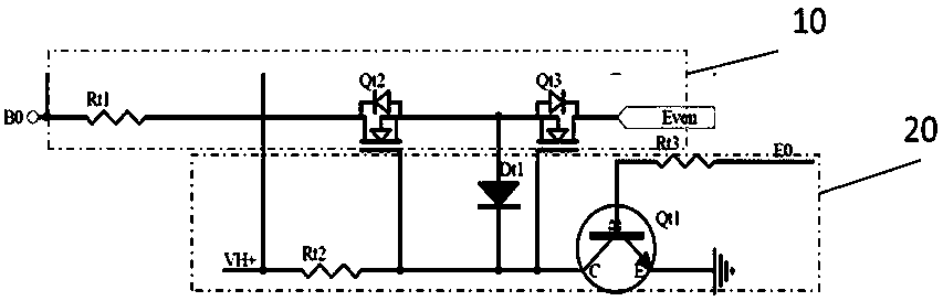
[0030] Embodiment 1-MOS switch driving circuit:

[0031] In this embodiment, Qt2 and Qt3 are NMOS transistors with a withstand voltage of 100v and a rated current of 2A, which are used in series battery packs below 100v. The battery pack voltage and battery cell balance require current. The high-voltage power supply VH+ is 200V, which is provided by a high-voltage pump twice the voltage of the battery pack. Here VH+ can also be provided by a high-voltage charge pump or other high-voltage power sources, and its potential must be higher than that of the positive electrode of the battery pack. The MOS gate charging resistor Rt2 (1 megohm) is connected to the high voltage power supply VH+. The gate clamping diode Dt1 is a 10V zener diode, and its regulated voltage value is greater than the MOS turn-on threshold voltage and lower than the maximum withstand voltage of the gate. The triode Qt1 is an npn tube with a withstand voltage of 300v and a rated current of 0.5A. Its withsta...

Embodiment 2

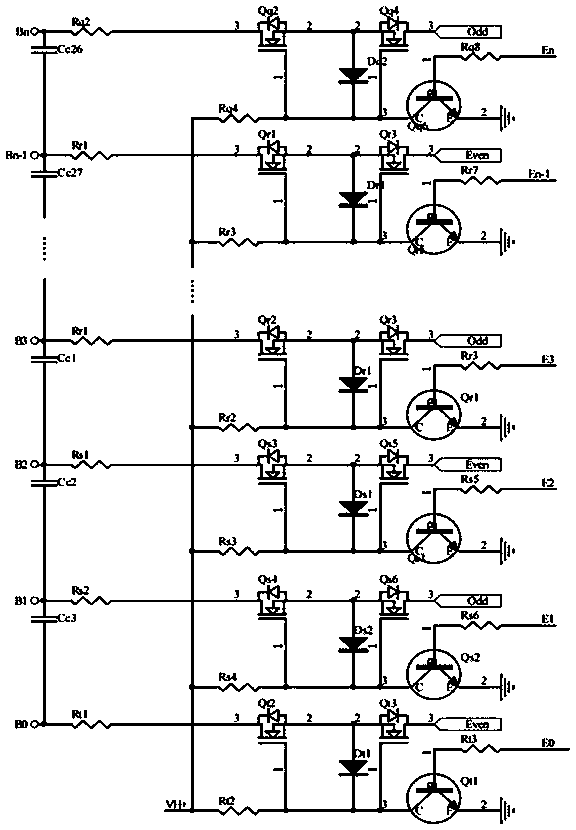
[0033] Embodiment 2-MOS switch driving circuit array:

[0034] In this embodiment, a series battery pack of 21 cells is connected. There are 22 circuits of Embodiment 1 to form an array. The negative pole of battery cell 1 is marked as B0, the positive pole of battery cell 1 is also the negative pole of battery cell 2, marked as B1, and so on, the negative pole of battery cell 21 is marked as B20, and the positive pole of battery cell 21 is marked as B21. When the mark number is 0 or an even number, it is connected to the output node Even, and when the mark number is odd, it is connected to the output node Odd. It is known that the fully charged voltage of each cell of the series battery pack is 4.2V, and the charged voltage of the entire series battery pack is 88.2V, so it is very suitable to select an NMOS with a withstand voltage of 100V in the circuit.


PUM


Abstract

The invention discloses an MOS switch drive circuit for a series battery pack battery management system. The MOS switch drive circuit is located between any of cells of a series battery pack and a switch array voltage polarity conversion circuit of the battery management system to complete cell channel gating with an active balanced cell balancing function or cell voltage measurement function, andis characterized in that an MOS grid voltage in the circuit is controlled by utilizing adaptive voltage suspension, and controls different potential voltages by a control signal. The invention also provides an array consisting of the circuit; and the array utilizes a same set of circuit and serves requirements of cell voltage measurement and cell balancing, thereby simplifying a structure of thedrive circuit, and an ultimate purpose of reducing the cost and improving the system reliability is achieved.

Description

technical field [0001] The present invention relates to a battery management system (BMS), in particular to a MOS switch drive circuit and an array thereof applied in a serial battery pack management system. Background technique [0002] Due to the inconsistency of battery cell parameters in series battery packs, there will be a problem of unbalanced battery power with use. If the battery cells are not properly balanced in time, the available power of the entire battery pack will become lower and lower, until it seriously affects normal use. (For example, affecting the cruising range of electric vehicles). Therefore, the battery management systems in the prior art all treat the cell equalization function as an important core function of the battery management system. Among them: active equalization technology can realize energy lossless or low-loss transfer between different cells, and has the advantages of large equalization current, low heat generation, and high equalizat...

Claims


Application Information

Patent Timeline
Patent Type & Authority Applications(China)
IPC IPC(8): H03K17/687H01M10/42
CPCH01M10/4207H01M10/425H03K17/6871H01M2010/4271H03K2217/0054Y02E60/10
Inventor 付允念
Owner 付允念
Why Eureka
Try Eureka