High-speed water lubrication dynamic pressure spiral groove bearing electric spindle

A spiral groove and water-lubricated technology, which is applied in the direction of large fixed members, metal processing machinery parts, maintenance and safety accessories, etc., can solve the problem that it is difficult to form a dynamic pressure water film on the bearing, it is not suitable for high-speed precision electric spindle, and the service life of the bearing is shortened, etc. problems, achieve good static and dynamic characteristics, significant dynamic pressure effect, and reduce viscous resistance

Inactive Publication Date: 2019-01-04
SOUTHEAST UNIV
View PDF5 Cites 3 Cited by
  • Summary
  • Abstract
  • Description
  • Claims
  • Application Information

AI Technical Summary

Problems solved by technology

[0004] However, in the initial stage of electric spindle start-up, it is often difficult for water-lubricated dynamic pressure bearings to form a dynamic pressure water film, and there is a risk of wear and tear on the bearings
At present, ordinary cylindrical water-lubricated dynamic pressure bearings have been widely used in water pumps, ships and other fields, but such ordinary cylindrical water bearings are mostly made of rubber materials, and the rotation accuracy is low, so they are not suitable for high-speed precision electric spindles; at the same time, ordinary Cylindrical dynamic pressure bearings will experience serious instability under small eccentricity
The water lubricating medium has low viscosity and no pollution, and has strong corrosion and cavitation under high-speed conditions, thus shortening the service life of the bearing

Method used


Image

  • High-speed water lubrication dynamic pressure spiral groove bearing electric spindle
  • High-speed water lubrication dynamic pressure spiral groove bearing electric spindle
  • High-speed water lubrication dynamic pressure spiral groove bearing electric spindle

Examples


Embodiment Construction

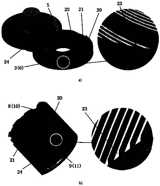
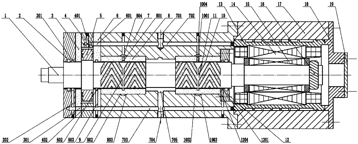
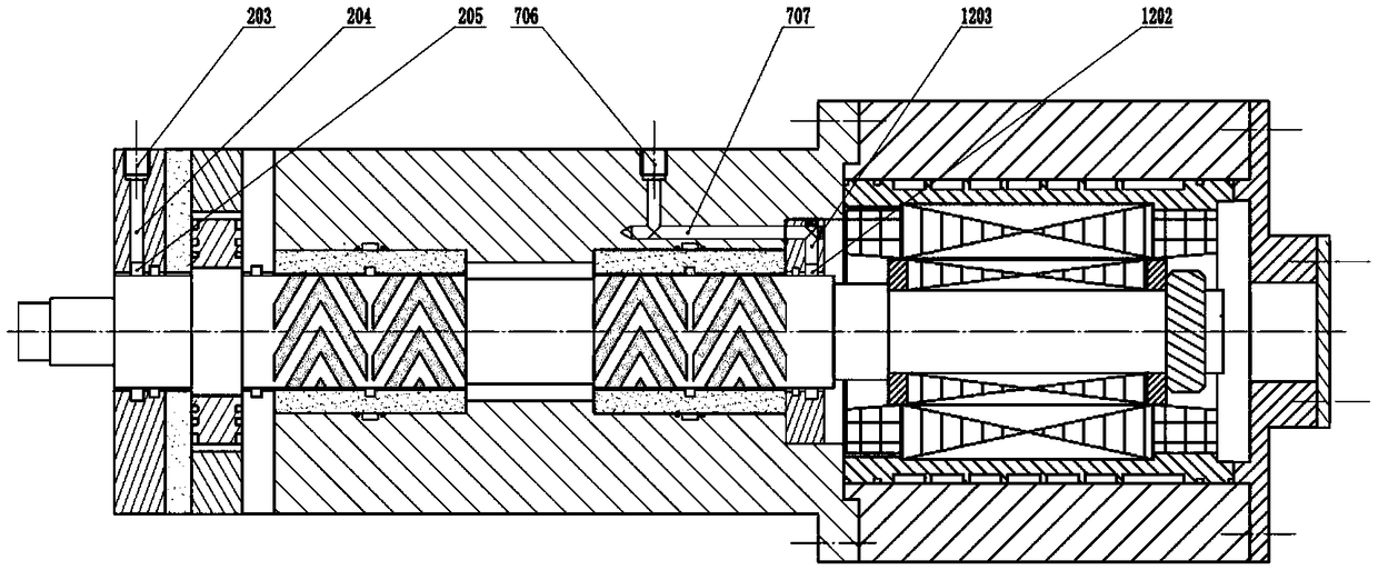
[0032] A high-speed water-lubricated dynamic pressure spiral groove bearing electrical spindle of the present invention includes a housing 7, a dynamic pressure spiral groove radial bearing and a thrust bearing arranged in the housing 7, and a radial-thrust bearing combined support The main shaft 1, the non-contact front and rear gas injection sealing rings arranged at the end of the bearing, the motor rotor 15 installed with the conical surface of the main shaft 1, the cooling water jacket 13 arranged outside the motor stator 14, and peripheral equipment. Both the dynamic pressure spiral groove radial bearing and the thrust bearing use water as lubricant, and the peripheral equipment includes frequency converter, air supply system and cooling water supply system, etc.

[0033]The main shaft 1 is jointly supported by a dynamic pressure spiral groove radial-thrust bearing. Among them, the dynamic pressure spiral groove radial bearing includes a front radial bearing and a rear r...


PUM


Abstract

The invention discloses a high-speed water lubrication dynamic pressure spiral groove bearing electric spindle. The spindle comprises a shaft neck, a radial bearing bush, a thrust disc, a thrust bearing bush, a spindle body, a gas injection sealing ring, a motor stator, a motor rotor, a cooling water jacket, a shell and peripheral equipment. Water serves as lubricant of a radial (thrust) bearing,spiral grooves are engraved in the shaft neck and in the thrust disc, and an anti-drag micro-textures are machined in a table area; the radial (thrust) bearing bush is made of special carbon graphite,and a Ta-Si-based nano composite coating is prepared on the surface of the neck shaft (thrust disc); the spindle body adopts dynamic pressure spiral groove radial supporting and thrust bearing mixingsupporting, the special non-contact gas injection sealing ring is designed at the ends of the bearings, and the spindle body is driven by a rare earth permanent magnet brushless direct current motor;and the motor stator is cooled through the cooling water jacket. The spindle has the advantages that the temperature rise of the bearings is low, the friction power consumption is low, the rotation precision is high, the stability is good, the cavitation erosion resistance is high, pollution is avoided, and the spindle is particularly suitable for a high-speed precision machining machine tool.

Description

technical field [0001] The patent of the invention relates to a high-speed water-lubricated dynamic pressure spiral groove bearing electric spindle, which belongs to the field of high-speed machining machine tools. Background technique [0002] Compared with traditional rolling bearing electric spindles and oil-lubricated bearing electric spindles, water-lubricated hydrostatic bearing electric spindles have outstanding advantages such as high rotation accuracy, small friction and wear, low temperature rise, high speed, long life, and no pollution. In recent years, This type of electric spindle has become one of the research hotspots in the high-speed machining machine tool industry. It should be noted that water-lubricated hydrostatic bearings rely on an external supply system to deliver high-pressure water, and regulate the pressure in the hydrostatic chamber through a throttle to form a hydrostatic lubricating film to withstand external loads. That is to say, the water-lu...

Claims


Application Information

Patent Timeline
Patent Type & Authority Applications(China)
IPC IPC(8): B23B19/02B23Q11/12
CPCB23Q1/70B23Q11/121B23Q11/127
Inventor 蒋书运张少文
Owner SOUTHEAST UNIV
Why Eureka
Try Eureka