Grinding wheel route generation method for low-speed servo grinding of free-form surface

A path generation and grinding wheel technology, which is applied to the parts of grinding machine tools, grinding frame, grinding bed, etc., can solve the problems of deterioration of processing quality, time-consuming processing, and no calculation method of grinding wheel grinding path, etc. Achieve the effects of high processing efficiency, high processing surface precision, and guaranteed stability

Active Publication Date: 2019-01-04
TIANJIN UNIV
View PDF5 Cites 6 Cited by
  • Summary
  • Abstract
  • Description
  • Claims
  • Application Information

AI Technical Summary

Problems solved by technology

However, for the circular aperture optical free-form surface with small diameter and obvious rotation characteristics, this processing method is not only time-consuming, but also the processing quality is deteriorated due to the discontinuous feeding of the tool, while the grinding method based on slow tool servo It can overcome these shortcomings and is very suitable for processing such optical free-form surfaces
However, the relevant research at home and abroad has not provided the relevant grinding wheel path calculation method, so it is necessary to develop a grinding wheel path generation method for slow tool servo grinding

Method used


Image

  • Grinding wheel route generation method for low-speed servo grinding of free-form surface
  • Grinding wheel route generation method for low-speed servo grinding of free-form surface
  • Grinding wheel route generation method for low-speed servo grinding of free-form surface

Examples


Embodiment approach 1

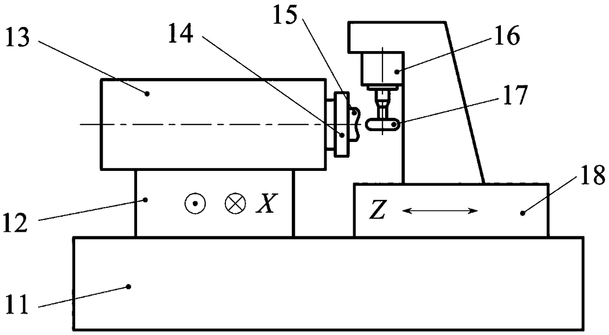
[0046] The structural layout of the machine tool in this embodiment is as follows: figure 1 As shown, the grinding wheel adopts a vertical structure. During processing, the workpiece 15 is adsorbed on the vacuum chuck 14, and is driven by the workpiece spindle (i.e., the C axis) to perform an angle-controllable rotary motion. The annular grinding wheel 17 is driven by the high-speed grinding spindle 16 to perform high-speed rotation, and the X-axis of the machine tool slides The plate 12 moves positively towards the X-axis, and the Z-axis sliding plate 18 performs feed motion with the rotation of the C-axis and the movement of the X-axis under the control of the machining program, so that the grinding process of the free-form surface can be realized. Among them, planning the relationship between the movement of the X and Z axes and the rotation angle of the C axis according to the geometric parameters of the free-form surface and the grinding wheel is a key issue in ultra-prec...

Embodiment approach 2

[0063] The structural layout of the machine tool in this embodiment is as follows: Figure 5 As shown, the grinding wheel adopts a horizontal structure. During processing, the workpiece 57 is adsorbed on the vacuum chuck 58, and is driven by the workpiece spindle (i.e., the C axis) to perform an angle-controllable rotary motion. The annular grinding wheel 56 is driven by the high-speed grinding spindle 54 to perform high-speed rotation, and the X-axis of the machine tool slides The plate 53 moves in the positive direction of the X-axis, and the Z-axis sliding plate 55 performs a feed motion with the rotation of the C-axis and the movement of the X-axis under the control of the machining program, so that the grinding process of the free-form surface can be realized. Among them, planning the relationship between the movement of the X and Z axes and the rotation angle of the C axis according to the geometric parameters of the free-form surface and the grinding wheel is a key issu...

Embodiment 1

[0080] freeform surface

[0081]

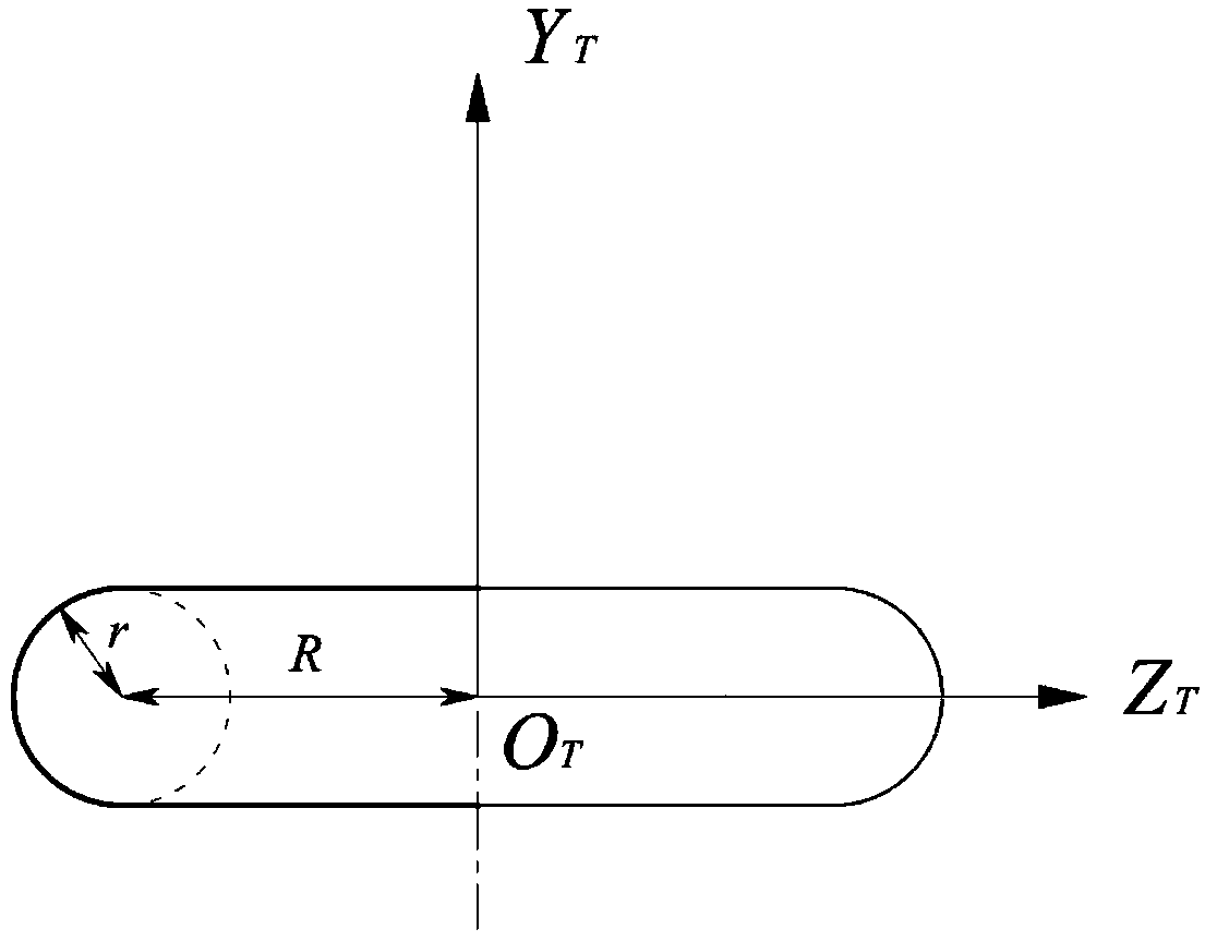
[0082] For example, using the method of Embodiment 1 to plan the machining path of the free-form surface, the geometric parameters of the annular grinding wheel are R=11 mm, r=1 mm, and the pitch of the equidistant helix is ​​set to 1 mm. The corresponding relationship between the generated tool control point X coordinate and Z coordinate and the rotation angle θ is as follows: Figure 8 As shown, the dotted line in the figure represents the X coordinate of the tool control point, and the solid line represents the Z coordinate.


PUM


Abstract

The invention relates to a grinding wheel route generation method for low-speed servo grinding of a free-form surface. A plane perpendicular to the Z axis of a workpiece coordinate system is established at the position, a certain distance zd above a to-be-machined free-form surface, in the workpiece coordinate system; an isometric helical line is generated in the plane and is discretized, and points obtained after discretization are converted into a cylindrical coordinate system form (rho, theta, zd); the to-be-machined free-form surface is rotated around the Z axis by the angle theta; and theminimum distance delta, between the grinding wheel machining curved surface and the rotated to-be-machined free-form surface in the Z direction, at the position of each point on the isometric helicalline is calculated, and the coordinate of the grinding wheel control point is obtained to be (rho, 0, zd-theta). A grinding wheel is an annular grinding wheel. The axis of the grinding wheel is perpendicular to the axis of a workpiece rotation shaft. According to the method, the projection drive track of the grinding wheel control point is generated preferentially, and stability of the feeding movement, in the X direction, of the grinding wheel is ensured; and the machining efficiency is higher, and precision of machined surfaces is higher.

Description

technical field [0001] The invention belongs to the technical field of ultra-precision machining and complex part manufacturing, and relates to a grinding wheel path generation method based on slow-speed slide plate servo grinding of free-form surfaces. Background technique [0002] Since the 1980s, with the development of astronomy, communications, microelectronics, and aerospace and other fields, higher requirements have been placed on the performance, imaging quality and structure of optical systems. Traditional optical systems using spherical or aspherical surfaces are not only complex in structure and bulky, but also difficult to meet high standards of imaging quality and optical performance requirements. The use of optical free-form surfaces can provide optical designers with great design freedom. Using one or a few optical free-form surfaces can replace multiple spherical or aspherical components, which not only simplifies the structure of the optical system, but also...

Claims


Application Information

Patent Timeline
Patent Type & Authority Applications(China)
IPC IPC(8): B24B1/00B24B19/00B24B41/06B24B41/02B24B47/20
CPCB24B1/00B24B19/00B24B41/02B24B41/06B24B47/20
Inventor 闫广鹏房丰洲
Owner TIANJIN UNIV
Why Eureka
Try Eureka