Ultra-precision grinding machine tool for small-size thin-walled complicated structure part

A complex structure, ultra-precision technology, applied in the direction of grinding machine parts, grinding frame, grinding machine bed, etc., can solve the problems of ultra-precision grinding processing difficulties, to ensure the grinding quality, achieve ultra-precision Grinding effect

Active Publication Date: 2017-06-13
HARBIN INST OF TECH
View PDF5 Cites 11 Cited by
  • Summary
  • Abstract
  • Description
  • Claims
  • Application Information

AI Technical Summary

Problems solved by technology

[0004] The present invention aims at the difficult problem of ultra-precision grinding of small-sized thin-walled complex structural parts with inner concave surface, and proposes a machine tool for ultra-precision grinding of small-sized thin-walled complex structural parts

Method used


Image

  • Ultra-precision grinding machine tool for small-size thin-walled complicated structure part
  • Ultra-precision grinding machine tool for small-size thin-walled complicated structure part
  • Ultra-precision grinding machine tool for small-size thin-walled complicated structure part

Examples


specific Embodiment approach 1

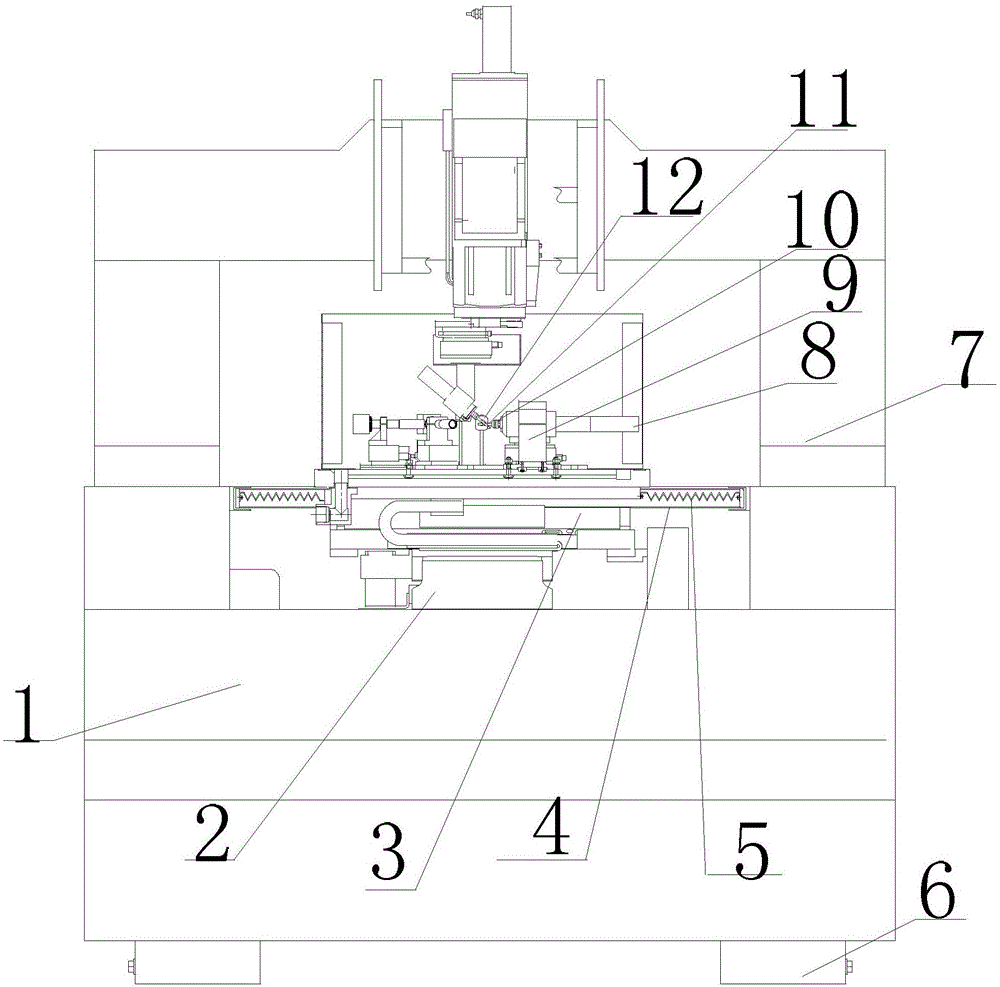
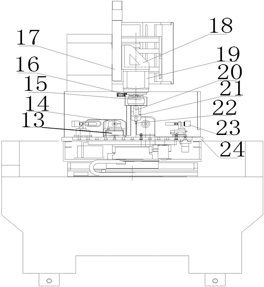
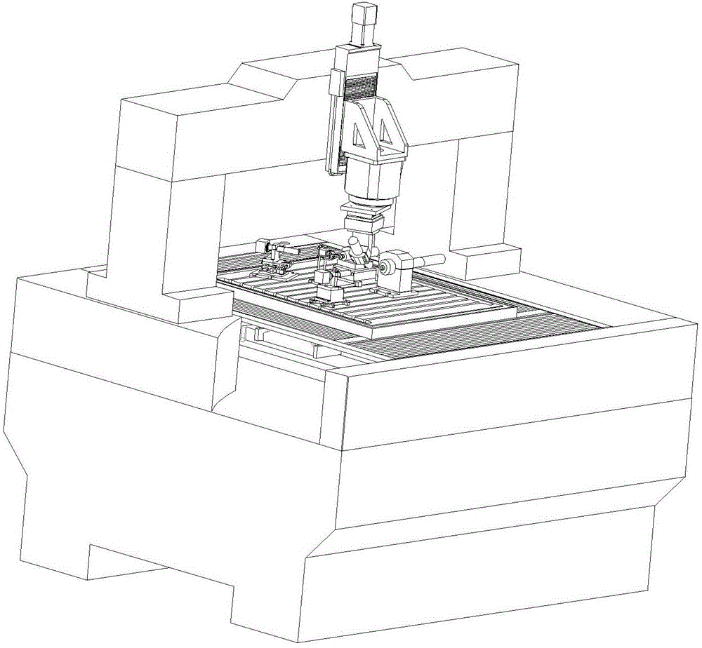
[0019] Specific implementation mode 1. Combination Figure 1 to Figure 3 Describe this embodiment, the machine tool for ultra-precision grinding of small-sized thin-walled complex structural parts described in this embodiment, it includes a machine tool base 1, a Y-axis linear motion platform 2, an X-axis linear motion platform 3, and an organ shield bracket 4. Organ protective cover 5, vertical structural parts 7, workpiece spindle 8, workpiece spindle fixing device 9, dressing electrode spindle 10, EDM dressing tool electrode 11, EDM dressing power supply device 12, ultra-precision linear motion platform 13, dressing Electrode spindle fixing device 14, ultra-precise linear positioning platform 15, one-dimensional precision fine-tuning displacement platform 16, Z-axis motion platform 17, turntable connector 18, direct drive precision turntable 19, grinding wheel spindle 20, grinding wheel spindle fixing device 21, small diameter Hemispherical head grinding wheel 22, CCD tool ...

specific Embodiment approach 2

[0031] Specific embodiment 2. This embodiment is a further description of the machine tool for ultra-precision grinding of small-sized thin-walled complex structural parts described in specific embodiment 1 or 2. The stroke of the Y-axis linear motion platform 2 is 300mm, and the positioning accuracy is ±0.5μm, straightness is 2.25μm.

specific Embodiment approach 3

[0032] Specific embodiment three. This embodiment is a further description of the machine tool for ultra-precision grinding of small-sized thin-walled complex structural parts described in specific embodiment one or two. The stroke of the X-axis linear motion platform 3 is 200mm, and the positioning accuracy is ±0.5μm, straightness is 2.25μm.


PUM

PropertyMeasurementUnit
Diameteraaaaaaaaaa

Abstract

The invention discloses an ultra-precision grinding machine tool for a small-size thin-walled complicated structure part, belongs to the technical field of precision and ultra-precision machining, and aims at solving the problems that ultra-precision grinding of the small-size thin-walled complicated structure part with a concave surface is relatively difficult. The part is machined by adopting a small-size ball grinding wheel in an oblique shaft grinding manner; a grinding wheel spindle is arranged on a Z-axis motion platform through a turn table to form an oblique shaft grinding device; and an X motion platform and a Y motion platform form a precise two-dimensional device in a ''cross'' stacking manner to achieve two-dimensional planar motion. The motion platforms are controlled through a multi-axis control system to achieve four-axis linkage to form a machining track of the part, and interference in the machining process is avoided through coordination with spindle inclination and turn table rotation. The ultra-precision grinding machine tool has a grinding station and an electric spark grinding wheel in-situ trimming station, and in-situ trimming of the ball grinding wheel in the machining process is achieved. The ultra-precision grinding machine tool is suitable for ultra-precision grinding for the small-size thin-walled complicated structure part.

Description

technical field [0001] The invention belongs to the technical field of precision and ultra-precision processing. Background technique [0002] At present, precision and ultra-precision processing technology occupies an important position in related fields such as cutting-edge products, defense industry and microelectronics industry. Relevant industries have also put forward higher and higher processing requirements for the required parts, not only requiring high surface accuracy, surface roughness and low sub-surface damage, but also more complex shapes and diversified materials. , in addition to the traditional plastic metal materials, but also to the development of brittle non-metallic materials. With the continuous development of ultra-precision grinding technology, especially the super-abrasive grinding technology with many advantages, it has played an irreplaceable role in the processing of such parts. [0003] In the field of aerospace, related core components also h...

Claims


Application Information

Patent Timeline
IPC IPC(8): B24B19/00B24B27/00B24B41/02B24B51/00B24B53/06B24B53/12B24B41/04B24B49/12B24B47/20B24B47/22
CPCB24B19/00B24B27/0023B24B41/02B24B41/04B24B47/20B24B47/22B24B49/12B24B51/00B24B53/06B24B53/12
Inventor 陈明君王廷章刘赫男程健张杰高万彬方针于波
Owner HARBIN INST OF TECH
Why Eureka
Try Eureka