Vibration resisting small carpentry edge polishing machine

An edge trimming machine and anti-vibration technology, which is applied to machine tools, manufacturing tools, and grinding feed motions suitable for grinding workpiece edges. It can solve problems such as low work stability, inability to meet production needs, and uneven force. , to achieve the effect of improving work stability, high work stability, and improving the effect of trimming

Inactive Publication Date: 2019-01-04
湖州欧宝木业有限公司
View PDF0 Cites 2 Cited by
  • Summary
  • Abstract
  • Description
  • Claims
  • Application Information

AI Technical Summary

Problems solved by technology

[0002] Due to the low surface roughness of the side walls around the sheared boards, accompanied by defects such as burrs and raised surfaces, the sheared wood boards cannot meet the needs of production, which leads to the need for the manufacturer to use a trimming machine to reverse the wood boards before processing the semi-finished wood boards. edge, so that the side wall surface of the plank can have a good finish
However, when the trimming machine used for small pieces of wood is working, workers need to manually push and squeeze the wood, so that the wood can be attached to the grinding head of the trimming machine under the extrusion effect and realize chamfering; This method not only consumes a lot of manual labor, but also causes vibration or uneven force due to the cutting force of the grinding head when the workers press the wood, which seriously affects the surface finish of the wood after cutting.
In addition, because some wood will form a trapezoidal shape after cutting, the side of the wood cannot be repaired by manual pressing, so that the long sides of the wood will be parallel to each other after repairing, further reducing the Trimming effect of trimming machine on wood
Therefore, the existing trimming machine has the problems of low working stability and poor trimming effect when trimming the wood side wall.

Method used


Image

  • Vibration resisting small carpentry edge polishing machine
  • Vibration resisting small carpentry edge polishing machine

Examples


Embodiment Construction

[0012] The present invention will be further described below in conjunction with the accompanying drawings and embodiments, but not as a basis for limiting the present invention.

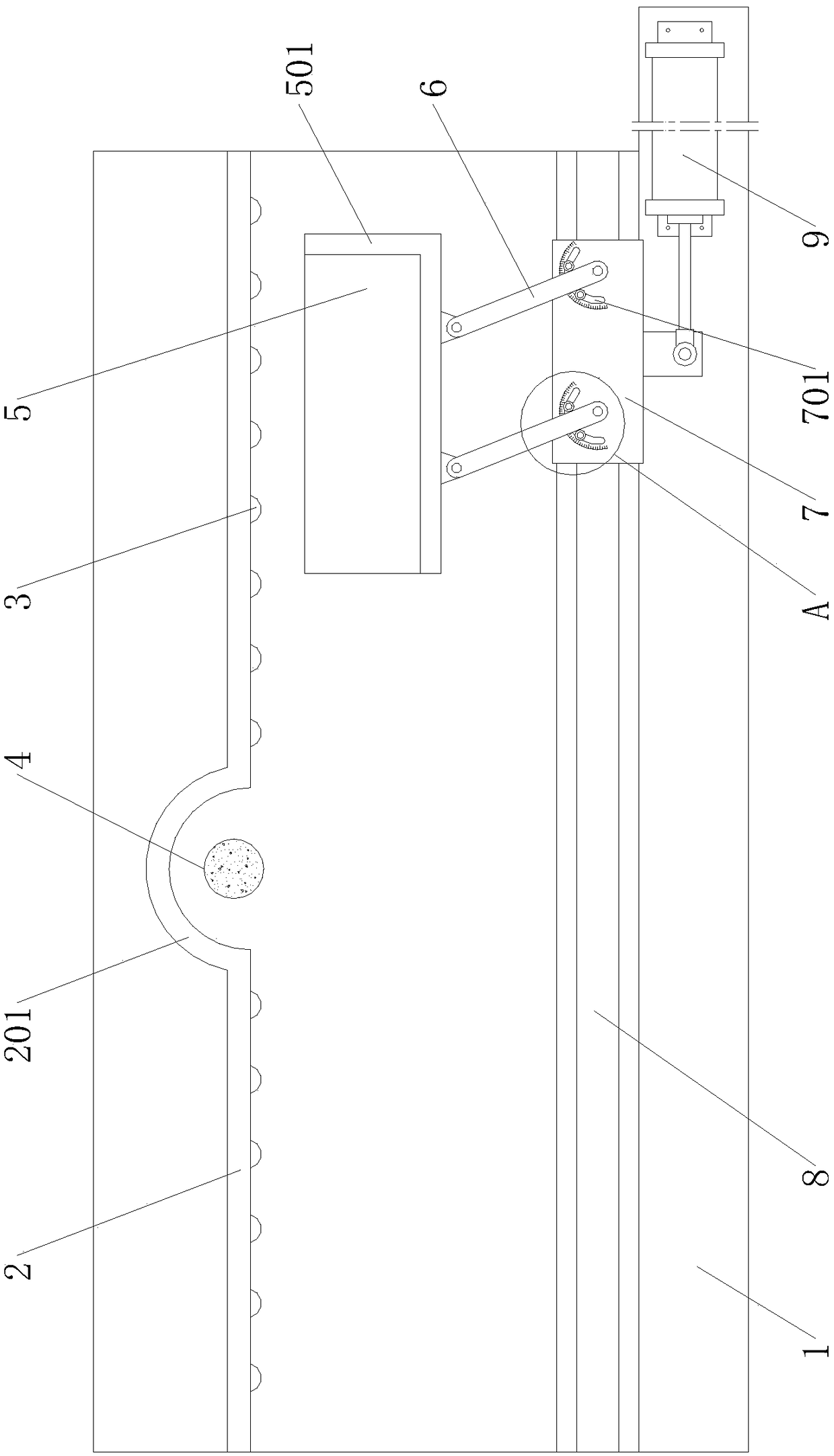
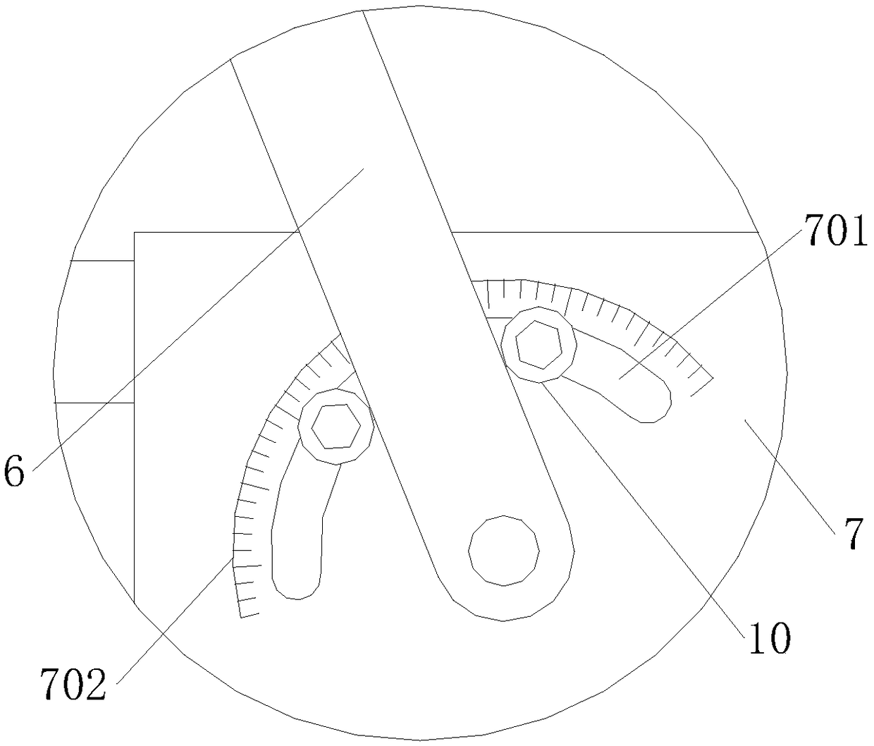
[0013] Example. An anti-vibration small woodworking trimming machine, which is composed of figure 1 As shown, including workbench 1, a limit plate 2 is provided on one side of workbench 1, and a plurality of rotatable balls 3 are arranged side by side on the limit plate 2, and one end of the ball 3 extends to the outside of the limit plate 2, and the limit plate 2 The middle part is provided with an arc-shaped opening 201, and a rotatable grinding head 4 is arranged in the arc-shaped opening 201. The lower end of the grinding head 4 is connected with a rotating motor located in the workbench 1. The lower end of the moving plate 5 is placed on the workbench 1 via a plurality of rollers. The horizontal position of the traversing plate 5 can be adjusted arbitrarily on the workbench 1. An L-shaped baff...


PUM


Abstract

The invention discloses a vibration resisting small carpentry edge polishing machine. The vibration resisting small carpentry edge polishing machine comprises a working platform. A limiting plate is arranged on one side of the working platform. A plurality of rotary balls are arranged on the limiting plate side by side. An arc opening is formed in the middle of the limiting plate. A rotary polishing head is arranged in the arc opening. A sidesway plate is arranged on the outer side of the limiting plate. The lower end of the sidesway plate is positioned at the working platform through a plurality of pulleys. An L-shaped baffle is arranged on one side of the sidesway plate. Push rods are rotatably connected with the outer side of the baffle. A push block is rotatably connected with the endsof the push rods. The lower end of the push block is connected with the working platform by a linear slide rail. A push air cylinder is connected with one side of the push block. Arc mounting holes are formed in the push block. The arc mounting holes are internally provided with locking assemblies matched with the push rods. The vibration resisting small carpentry edge polishing machine has the characteristics that working stability is high, and the edge polishing effect is excellent.

Description

technical field [0001] The invention relates to a woodworking edge trimming machine, in particular to a vibration-proof small woodworking edge trimming machine. Background technique [0002] Due to the low surface roughness of the side walls around the sheared boards, accompanied by defects such as burrs and raised surfaces, the sheared wood boards cannot meet the needs of production, which leads to the need for the manufacturer to use a trimming machine to reverse the wood boards before processing the semi-finished wood boards. edge, so that the side wall surface of the plank can have a good finish. However, when the trimming machine used for small pieces of wood is working, workers need to manually push and squeeze the wood, so that the wood can be attached to the grinding head of the trimming machine under the extrusion effect and realize chamfering; This method not only consumes a lot of labor, but also causes vibration or uneven force due to the cutting force of the gr...

Claims


Application Information

Patent Timeline
Patent Type & Authority Applications(China)
IPC IPC(8): B24B9/18B24B41/00B24B49/00
CPCB24B9/18B24B41/00B24B41/005B24B49/00
Inventor 沈国平
Owner 湖州欧宝木业有限公司
Why Eureka
Try Eureka