Dam-free water flow turbine power generation system

A power generation system and water flow technology, applied in hydroelectric power generation, ocean energy power generation, engine components, etc., can solve problems affecting surrounding residents and power station staff, lack of flexibility, and inability to move at will.

Inactive Publication Date: 2019-01-04
时扬
View PDF7 Cites 3 Cited by
  • Summary
  • Abstract
  • Description
  • Claims
  • Application Information

AI Technical Summary

Problems solved by technology

[0002] At present, hydropower is mainly used for dam-building power stations. The purpose of dam-building is mainly to form high water head and high drop, that is, high potential energy power generation. Although its power generation efficiency is also high, the disadvantages are also obvious. First, dam-building After the water level rose, it directly led to the loss and changes of geological structure, ecology, farmland, cultural relics, etc., and even immigration, which caused irreversible impacts. Second, the cost of building dams was high. Third, the large drop caused loud noise. Affect the surrounding residents and power station staff. Fourth, the site selection of the power station is exquisite. It is not possible to build a power station anywhere at will. It lacks flexibility, is not portable enough, and cannot be moved at will.

Method used


Image

  • Dam-free water flow turbine power generation system
  • Dam-free water flow turbine power generation system
  • Dam-free water flow turbine power generation system

Examples


Embodiment 1

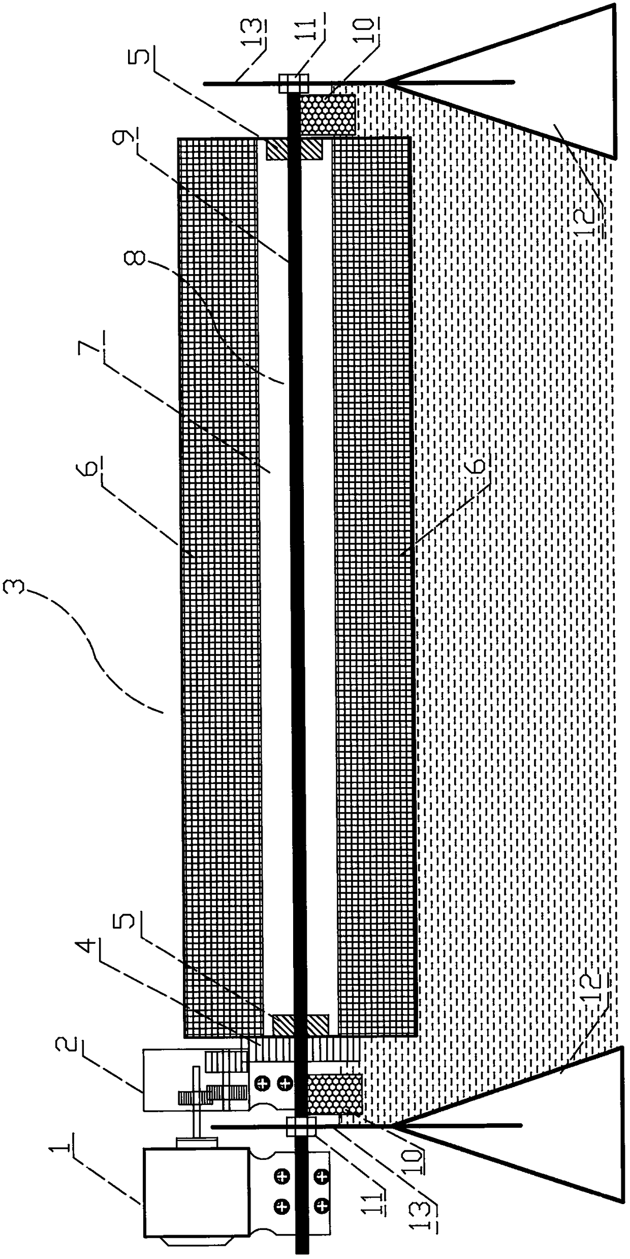
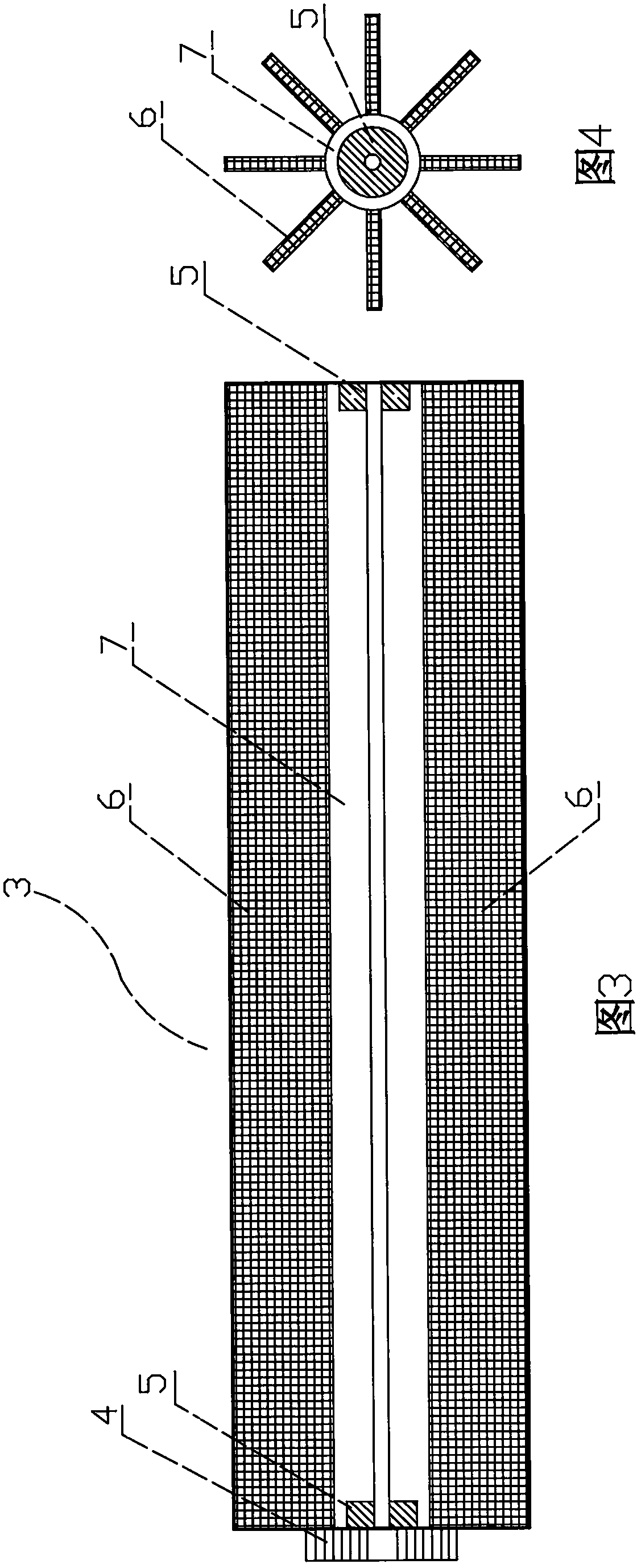
[0022] Such as figure 1 , figure 2 As shown, the power generation system mainly includes a generator 1, a speed change gear set 2, a barrage central shaft part 8, a turbine blade 3 and a stable support 12, wherein the barrage central shaft part 8 is perpendicular to the direction of water flow and half floats on the water surface. The middle axis part 8 of the barrage is kept supported under the action of the stable brackets 12 located at both ends of the river bank, and the turbine blade 3 placed on the middle axis part 8 of the river barrage rotates under the action of the impact of the water flow, thereby driving the speed change gear set 2 to run and finally generating electricity Machine 1 works to generate electricity.

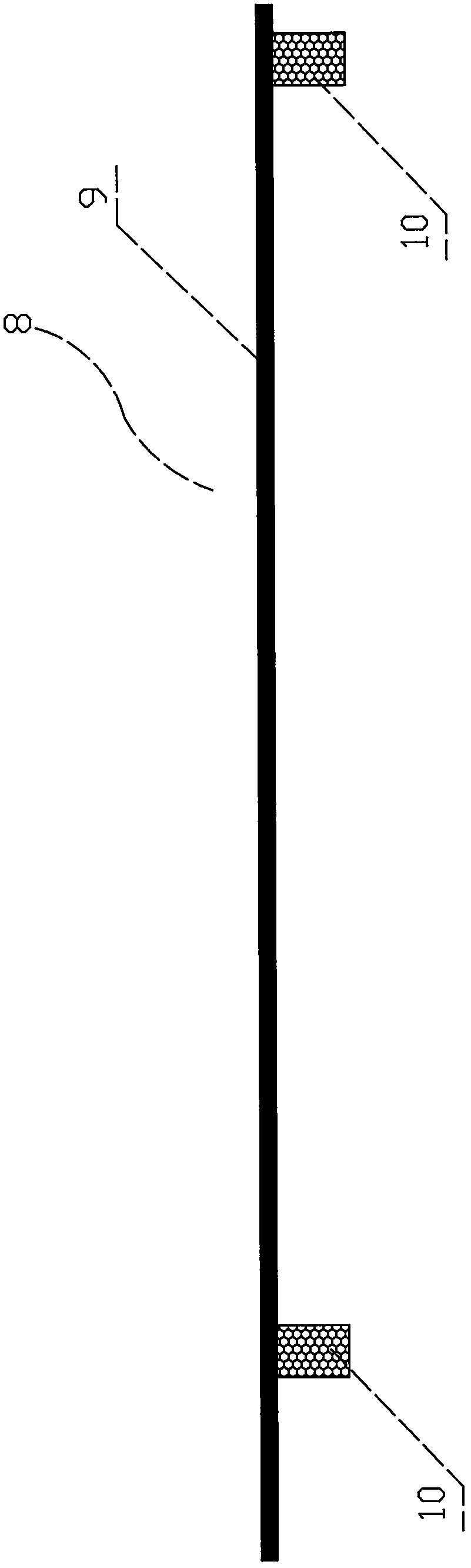
[0023] Such as figure 2 , image 3 with Figure 4 As shown, the barrage central axis part 8 is composed of the barrage central axis 9 and the floating depth control device 10. The central axis of the turbine blade 3 is hollow, that is, the hollow s...


PUM


Abstract

Water flow is fully utilizedin adam-free water flow turbine power generation system for directly impacting fan blades to operate, since the fan blades and the river surface are almost equal in width,huge impulse energy of the river section is greatly utilized for generating electricity after speed change, and thedam-free water flow turbine power generation system is provided. The system comprisesa generator, a change gear set, a river across center shaft part, the turbine fan blades and stable brackets; the river across center shaft part is perpendicular to the direction of water flow and half-floats on the water surface; the river across center shaft part retains the support state under the action of the stable brackets located at the two ends of a river bank; and the turbine fan bladesarranged on the river across center shaft part are rotated under the action of impact of water flow so as to drive the change gear set to operate, and finally the generator is enabled to operate andgenerate electricity.

Description

technical field [0001] The invention relates to a power generation system, in particular to a power generation system which utilizes water flow momentum to generate power. Background technique [0002] At present, hydropower is mainly used for dam-building power stations. The purpose of dam-building is mainly to form high water head and high drop, that is, high potential energy power generation. Although its power generation efficiency is also high, the disadvantages are also obvious. First, dam-building After the water level rose, it directly led to the loss and changes of geological structure, ecology, farmland, cultural relics, etc., and even immigration, which caused irreversible impacts. Second, the cost of building dams was high. Third, the large drop caused loud noise. Affect surrounding residents and power station staff. Fourth, the site selection of the power station is exquisite. The power station cannot be built anywhere at will. It lacks flexibility, is not porta...

Claims


Application Information

Patent Timeline
Patent Type & Authority Applications(China)
IPC IPC(8): F03B13/22F03B11/00
CPCF03B11/00F03B11/008F03B13/22Y02E10/20Y02E10/30
Inventor 时扬
Owner 时扬
Why Eureka
Try Eureka