
A method for measuring blade tip clearance based on microwave frequency sweep

A technology of blade tip clearance and measurement method, which is applied in the direction of measuring devices, instruments, and electric devices, etc., can solve the problems of resonance frequency point drift, measurement accuracy affected by temperature, etc., and achieve the effect of wide dynamic range and elimination of common mode error

Active Publication Date: 2020-04-10
善测(天津)科技有限公司
View PDF14 Cites 0 Cited by
  • Summary
  • Abstract
  • Description
  • Claims
  • Application Information

AI Technical Summary

Problems solved by technology

Based on the point-frequency resonant cavity sensor microwave tip clearance measurement system, the measurement of the tip clearance is realized by measuring the relationship between the fixed-frequency point voltage and the clearance, but the change of the ambient temperature will cause the resonance frequency point to drift, and the measurement accuracy is greatly affected by the temperature. It is necessary to adjust the measurement frequency point in real time according to the ambient temperature

Method used


Image

  • A method for measuring blade tip clearance based on microwave frequency sweep
  • A method for measuring blade tip clearance based on microwave frequency sweep
  • A method for measuring blade tip clearance based on microwave frequency sweep

Examples


Embodiment Construction

[0020] The present invention will be described below in conjunction with the accompanying drawings and embodiments.

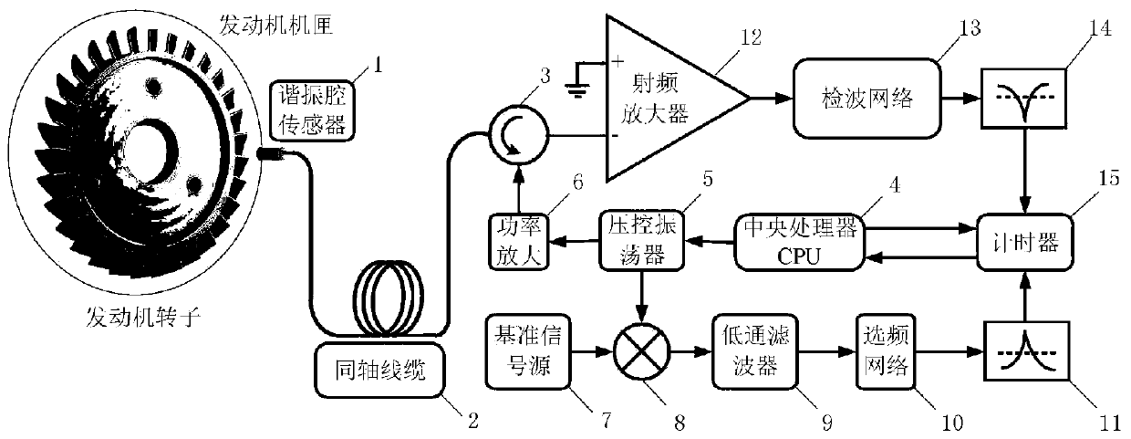
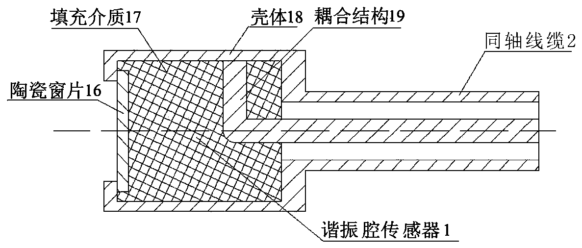
[0021] The present invention proposes a moving blade tip clearance measurement system based on the microwave frequency sweeping working mode, such as figure 1 As shown, it includes: resonant cavity sensor 1, coaxial cable 2, circulator 3, central processing unit (CPU) 4, voltage controlled oscillator (VCO) 5, radio frequency power amplifier 6, reference signal source 7, mixer 8. Low pass filter 9, frequency selection network 10, reference time discriminator 11, radio frequency low noise amplifier 12, detection network 13, resonance time discriminator 14, timer 15.

[0022] The central processing unit (CPU) 4 generates a voltage signal modulated by a sawtooth wave or a triangular wave to control a voltage-controlled oscillator (VCO) 5 to realize linear and fast frequency sweep. At the second level, output two channels of reference signals of the same frequency ...


PUM


Abstract

The invention relates to a microwave frequency sweep-based measurement method for a tip clearance. The method includes the following steps: a voltage-controlled oscillator VCO outputs two channel same-frequency same-phase reference signals and emission signals that are linear frequency-swept by a radio frequency wave band; the reference signal and a datum signal output by a datum signal source aremixed by a mixer; a mixing signal is filtered by a low-pass filter to remove a high-frequency sum frequency signal; a difference frequency signal is frequency-selected by a frequency selective network; the frequency selective network outputs a signal and triggers a datum time discriminator to identify a datum time; in addition, the amplified emission signals pass through a circulator, then a resonant cavity sensor projects microwave to a direction of a rotor shaft through a coaxial cable, and the circulator receives a signal reflected by a blade end face; the signal reflected by the blade endface is amplified by the circulator, and then a radio frequency carrier signal is filtered out in a detection network, and a resonance time discriminator is triggered to identify a resonance time; and a timer outputs time difference data to a CPU. The method can achieve high-precision measurement of the tip clearance under high temperature.

Description

technical field [0001] The invention relates to a method for measuring blade tip clearance based on microwave frequency sweep. Background technique [0002] Large rotating machinery such as aero engines and gas turbines are the "heart" of major key equipment such as aircraft and ships in the defense field. As the core working element of the moving blade, its state parameters directly affect the operation safety and work efficiency of major national defense equipment. Among them, under high temperature, high pressure and gas corrosion environment, the online measurement of the blade tip clearance parameters of the rotating blade is the key link to avoid the friction between the blade and the casing, ensure the safety of the engine, reduce the fuel consumption of the engine, and improve the efficiency of the compressor or turbine . The basic principle is to install the sensor on the rotating machine casing. When the moving blade rotates to the front of the sensor, the distan...

Claims


Application Information

Patent Timeline
Patent Type & Authority Patents(China)
IPC IPC(8): G01B7/14
CPCG01B7/14
Inventor 段发阶牛广越蒋佳佳叶德超程仲海
Owner 善测(天津)科技有限公司
Learn More