Converter control circuit, application and control method thereof

A converter control and control circuit technology, applied in control/regulation systems, DC power input conversion to DC power output, instruments, etc., can solve the problems of increased loss, large turn-on loss, low efficiency, etc., and achieve the effect of improving efficiency

Pending Publication Date: 2019-01-04
MORNSUN GUANGZHOU SCI & TECH
View PDF0 Cites 10 Cited by
  • Summary
  • Abstract
  • Description
  • Claims
  • Application Information

AI Technical Summary

Problems solved by technology

[0004] In boost mode and buck mode, only two mos tubes have switching action in any one cycle, while in buck-boost mode, all four mos tubes have switching action in one cycle, so in buck-boost mode In mode, the increased MOS tube switching loss will lead to lower efficiency;
[0005] In addition, limited by the characteristics of the semiconductor device itself, it takes a certain amount of time to turn on and off the mos tube. If the turn-on time is too short, it will cause a huge turn-on loss. Therefore, there is a minimum duty cycle limit in the existing control circuit. circuit or the maximum duty cycle limiting circuit, in this three-mode control scheme, the transition from boost mode or buck mode to buck-boost mode must have a duty cycle jump from zero to minimum duty cycle or from 1 jump The sudden change to the maximum duty cycle will cause an overshoot of the output voltage, making the transition process not smooth
[0006] Secondly, the traditional peak current control mode needs to sample the inductor current. Although there are solutions for non-destructive sampling of the inductor current in the prior art, the requirements for the circuit are relatively strict. The implementation of some solutions must rely on integrated mos tubes. The external circuit of the tube, the sampling current still depends on the resistance, which will inevitably lead to an increase in loss, resulting in lower efficiency

Method used


Image

  • Converter control circuit, application and control method thereof
  • Converter control circuit, application and control method thereof
  • Converter control circuit, application and control method thereof

Examples


Embodiment Construction

[0053] In order to better understand the design concept of the control circuit of the present invention, the specific implementation manners of the present invention will now be described in detail with reference to the accompanying drawings.

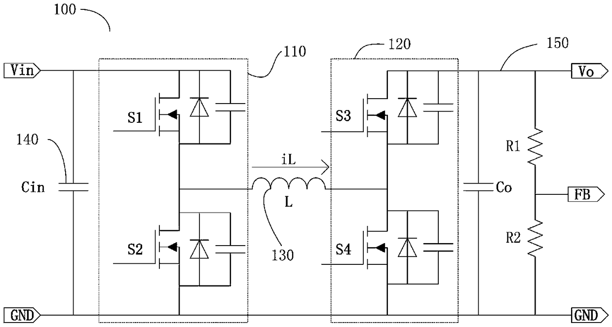
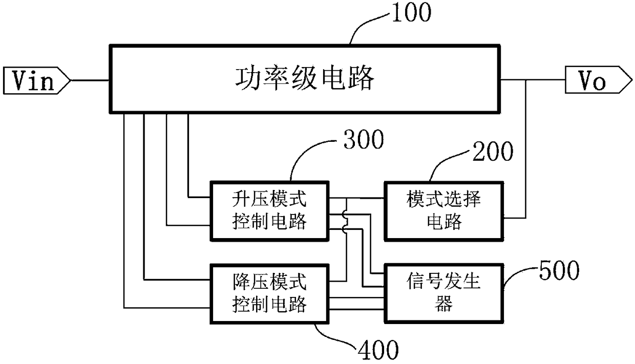
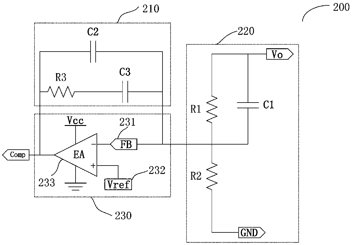
[0054] refer to figure 2 , is a schematic structural diagram of the control circuit of the boost-buck converter of the present invention, the boost-buck converter includes a power stage circuit 100, and its control circuit includes a mode selection circuit 200, a boost mode control circuit 300, a buck mode control circuit 400 and Signal generator 500.

[0055]The power stage circuit 100 is used to convert the input voltage Vin into a desired voltage value and output it, the mode selection circuit 200 is used to select the working mode required by the boost-buck converter according to the output voltage, and the boost mode control circuit 300 works When the input voltage is lower than the output voltage, it is used to increase the inpu...


PUM


Abstract

A switch control circuit, application and control method , the converter control circuit includes a signal generator, mode selection circuit, a step-down mode control circuit and a step-up mode control circuit, the signal generator is used for generating a reference signal required by the step-up mode control circuit and the step-down mode control circuit, A mode selection circuit generates a modeselection control signal according to the output voltage, A boost mode control circuit and a buck mode control circuit simultaneously receive a mode selection control signal, and compares them with their internal reference signals, and then select the operation mode required for the step-up and step-down converter, the present invention is applied to step-up and step-down converters in any period, The converter operates in only one mode, which means that only two power transistors have switching operation, which improves the efficiency of mode switching, and the mode switching is smoother when the input voltage and the output voltage are comparatively close to each other, and the boost mode control circuit and the buck mode control circuit alternately work.

Description

technical field [0001] The invention relates to a power supply circuit, in particular to a control circuit, application and control method of a DC-DC step-down converter with two working modes. Background technique [0002] Traditional non-isolated DC-DC converters are very mature, such as Buck converters, Boost converters and Buck-Boost converters, which are widely used in automotive, photovoltaic, industrial control, medical and handheld devices, especially in battery-powered In the system, because the battery voltage is low, isolation is not required, so the traditional non-isolated converter has obvious cost advantages and performance advantages. In a battery-powered system, the discharge of the battery is accompanied by a decrease in the battery voltage, and the battery voltage increases when the battery is charged. Therefore, a converter with boost and step-down functions is required. The traditional converter with step-up and step-down functions, namely Buck -Boost c...

Claims


Application Information

Patent Timeline
Patent Type & Authority Applications(China)
IPC IPC(8): H02M3/158
CPCH02M3/1582
Inventor 周瑜
Owner MORNSUN GUANGZHOU SCI & TECH
Why Eureka
Try Eureka