Combined roller sleeve, manufacturing method thereof and roller

A manufacturing method and technology of composite rolls, which are applied in the field of casting rolls and rolls, can solve problems such as easy loosening, cracks or falling blocks, and differences in physical and chemical properties, and achieve the effects of firm metallurgical bonding, increased service life, and good metallurgical bonding

Active Publication Date: 2019-01-11
HUNAN 3T NEW MATERIAL
View PDF7 Cites 2 Cited by
  • Summary
  • Abstract
  • Description
  • Claims
  • Application Information

AI Technical Summary

Problems solved by technology

[0004] However, due to the large difference in the physical and chemical properties of the two composite layers of the composite roller sleeve, there is inevitably an oxide layer on the surface of the seamless pipe. When the traditional casting composite process is used for product

Method used


Image

  • Combined roller sleeve, manufacturing method thereof and roller
  • Combined roller sleeve, manufacturing method thereof and roller

Examples


Embodiment 1

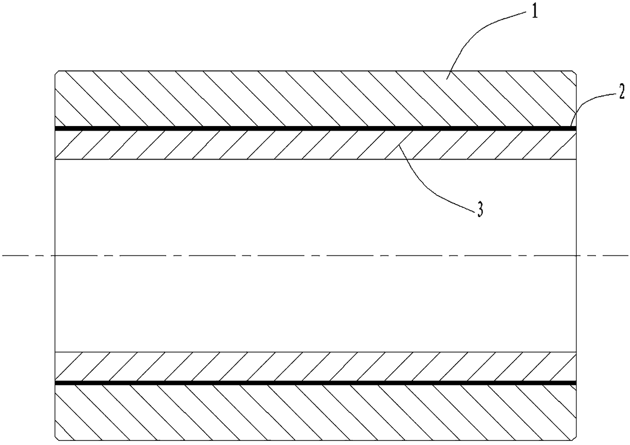
[0032] Please refer to figure 1, a composite roll sleeve of the present embodiment, the composite roll sleeve includes: an outer working layer 1, a composite transition layer 2 and an inner seamless pipe 3, the inner seamless pipe 3 is a prefabricated low-carbon seamless steel pipe, and the outer The working layer 1 is a cast-in-place wear-resistant alloy steel layer, and the composite transition layer 2 is a transition layer formed by the reaction of the thermite and slagging agent with the cast-in-place alloy liquid to form molten iron and the molten iron on the surface of the inner seamless pipe 3. The outer working layer 1, the composite transition layer 2 and the inner seamless pipe 3 are metallurgically bonded.

[0033] In a preferred embodiment, the outer working layer 1 has a thickness of 20 mm to 80 mm, the composite transition layer 2 has a thickness of 0.1 mm to 5.0 mm, and the inner seamless pipe 3 has a thickness of 10 mm to 50 mm. More preferably, the outer work...

Embodiment 2

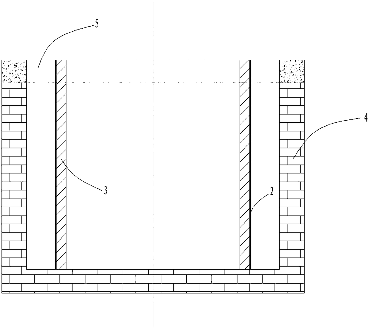
[0035] Please refer to figure 2 , the manufacturing method of a kind of composite roller cover of present embodiment, this manufacturing method comprises the following steps:

[0036] Step 1: Prepare a low-carbon seamless steel pipe with a predetermined size as the inner seamless pipe of the composite roll sleeve, and remove the dirt and oxide layer on the surface of the inner seamless pipe.

[0037] Step 2, mixing and stirring the thermite and slag forming agent to form cement, and evenly coating the outer surface of the inner seamless pipe 3, the coating thickness of the thermite and slagging agent is 0.5mm-5.0mm .

[0038] Step 3: install the inner layer seamless pipe 3 coated with thermite and slagging agent into the casting mold 4, and control the temperature of the inner layer seamless pipe 3 in the casting mold 4 at 0°C to 500°C .

[0039] Step 4: Pour the smelted alloy liquid from the casting port 5 into the casting mold 4. The temperature of the alloy liquid durin...

Embodiment 3

[0044] A roll in this embodiment includes the composite roll sleeve described in Embodiment 1; or, includes the composite roll sleeve manufactured by the manufacturing method described in Embodiment 2.


PUM

PropertyMeasurementUnit
Thicknessaaaaaaaaaa
Thicknessaaaaaaaaaa
Thicknessaaaaaaaaaa

Abstract

The invention discloses a combined roller sleeve, a manufacturing method thereof and a roller comprising the combined roller sleeve. The combined roller sleeve comprises an outer operation layer, a combined transition layer and an inner seamless pipe. The inner seamless pipe is a prefabricated low-carbon seamless steel pipe. The outer operation layer is a cast-in-place abrasion-resistant alloy steel layer. The combined transition layer is jointly formed by molten iron generated by reaction of thermite and a slag former and cast-in-place alloy liquid as well as molten iron on the surface layerof the inner seamless pipe. The outer operation layer, the combined transition layer and the inner seamless layer are metallurgically bonded. By coating the mixed coating of the thermite and the slagformer to the outer surface of the inner seamless pipe, the mixed coating has a chemical reaction with the high-temperature alloy liquid in the cast-in-place process of the outer operation layer, molten iron is generated, heat is released to melt the surface layer of the seamless steel pipe, the generated molten iron and the molten iron molten on the surface layer of the seamless steel pipe jointly form the combined transition layer, and therefore, firm combination of the outer operation layer and the inner seamless pipe can be achieved.

Description

technical field [0001] The invention relates to the technical field of casting rolls, in particular to a composite roll sleeve, a method for manufacturing the composite roll sleeve, and a roll comprising the composite roll sleeve. Background technique [0002] The roll is the most important consumable part in steel rolling production. It is also known as the "mother of steel". my country produces about 800,000 tons of rolls every year. Most of the currently used rolls are traditional integral rolls, and the sleeve-type composite rolls are currently only used in the field of bar and wire rolling. The sleeve-type composite roll is composed of a roll shaft and a roll sleeve. The roll sleeve is nested outside the roll shaft and is driven by the roll shaft to contact the steel billet to cause plastic deformation of the steel billet. The roll sleeve needs to withstand a large rolling force when in use, and there is a large sliding friction between the surface layer and the billet...

Claims


Application Information

Patent Timeline
IPC IPC(8): B21B27/03B22D19/16
CPCB21B27/03B22D19/16
Inventor 黄玲向勇曾麟芳李聚良
Owner HUNAN 3T NEW MATERIAL
Why Eureka
Try Eureka