
Laser head used for laser welding and facilitating to multi-directionally adjust angle

An angle adjustment and laser welding technology, applied in the field of laser heads, can solve the problems of inability to adjust the laser head and the workpiece, the inability to adjust the angle of the laser head, and the inability to prevent the accumulation of impurities in optical components, so as to reduce mechanical wear and reduce cleaning The effect of increasing the number of times and improving the efficiency of power transmission

Active Publication Date: 2019-01-11
四会市耀华精密机械有限公司
View PDF8 Cites 4 Cited by
  • Summary
  • Abstract
  • Description
  • Claims
  • Application Information

AI Technical Summary

Problems solved by technology

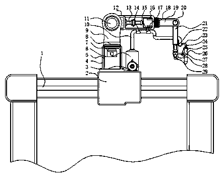
[0004] Aiming at the deficiencies of the prior art, the present invention provides a laser head for multi-directional angle adjustment for laser welding, which solves the problem that the position between the laser head and the workpiece cannot be adjusted well according to the position of the workpiece, and the position between the laser head and the workpiece cannot be adjusted well according to the workpiece. The angle of the laser head can be adjusted at the welding part, and the laser head cannot be moved according to the working conditions to increase the working range of the laser head. Rapid oxidation, a problem raised in the background art above

Method used


Image

  • Laser head used for laser welding and facilitating to multi-directionally adjust angle
  • Laser head used for laser welding and facilitating to multi-directionally adjust angle
  • Laser head used for laser welding and facilitating to multi-directionally adjust angle

Examples


Embodiment Construction

[0027] The following will clearly and completely describe the technical solutions in the embodiments of the present invention with reference to the accompanying drawings in the embodiments of the present invention. Obviously, the described embodiments are only some, not all, embodiments of the present invention.

[0028] In the description of the present invention, unless otherwise stated, the meaning of "plurality" is two or more; the terms "upper", "lower", "left", "right", "inner", "outer" , "front end", "rear end", "head", "tail", etc. indicate the orientation or positional relationship based on the orientation or positional relationship shown in the drawings, and are only for the convenience of describing the present invention and simplifying the description, rather than Nothing indicating or implying that a referenced device or element must have a particular orientation, be constructed, and operate in a particular orientation should therefore not be construed as limiting ...


PUM


Abstract

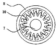
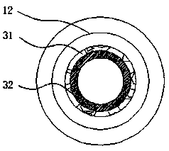
The invention discloses a laser head used for laser welding and facilitating to multi-directionally adjust an angle, relates to the technical field of welding, and specifically discloses a laser headused for laser welding and facilitating to multi-directionally adjust an angle. The laser head used for laser welding and facilitating to multi-directionally adjust the angle comprises a slide rail, an inner gear sleeve and a main gas pipe, wherein a slide block is installed at the middle part of the slide rail, and a stainless steel housing is installed above the slide block; a support rod is installed above the inner gear sleeve, and the inner gear sleeve is located above the stainless steel housing; and a servo motor is installed above the support rod. According to the laser head used for laser welding and facilitating to multi-directionally adjust the angle, through the cooperation among a compressor, the main gas pipe and a gas blowing pipe, inert gas in a gas storage tank can be effectively guided into the gas blowing pipe; when the laser head applies work on a workpiece, the gas blowing pipe blows the inert gas to a welding part of the workpiece, and the problem that the weldingpart of the workpiece is infirm and incapable of achieving the needed working effect because the welding part of the workpiece is rapidly oxidized, and impurities are easily generated at the weldingpart, is avoided.

Description

technical field [0001] The invention relates to the field of welding technology, in particular to a laser head for multi-directional angle adjustment for laser welding. Background technique [0002] In the pillar industries of the national economy such as metallurgy, shipbuilding, and automobiles, it is a common method to use lasers to weld relatively small metal sheets into relatively large sheets or to weld relatively short metal sheets or strips into relatively long sheets or strips. , this production process is called laser tailor welding. For example, when a roll rolls a relatively thick plate into a relatively thin plate, in order to continue production, lasers are widely used on the production line to weld the end of the previous roll of plate with the end of the rear plate. The front end of a roll of sheet metal is welded. This welding can make the rolling process continue for the desired time. This production process is called on-line laser tailor welding. [0003]...

Claims


Application Information

Patent Timeline
Patent Type & Authority Applications(China)
IPC IPC(8): B23K26/21B23K26/70
CPCB23K26/21B23K26/70B23K26/702
Inventor 杜都
Owner 四会市耀华精密机械有限公司
Learn More