
Automatic machine tool with B-axis control

An automatic machine tool, B-axis technology, applied in the direction of driving devices, manufacturing tools, metal processing machinery parts, etc., can solve the problems of low workpiece processing efficiency, poor accuracy, inconvenient disassembly and installation of power heads, etc., to shorten the processing cycle, improve Accuracy and processing efficiency, the effect of reducing the number of workpiece loading and unloading

Active Publication Date: 2019-01-11
津上精密机床(浙江)有限公司
View PDF5 Cites 1 Cited by
  • Summary
  • Abstract
  • Description
  • Claims
  • Application Information

AI Technical Summary

Problems solved by technology

[0003] The machine tools in the prior art usually have a main shaft, a sub-spindle, and a tool holder. When processing a workpiece, usually only some simple processing can be performed, such as punching a positive hole on the workpiece. , it is necessary to manually adjust the angle of the power head on the tool holder, or the workpiece has been sent to another machine tool for further drilling, tapping and milling. Due to the inconvenient disassembly and installation of the power head, the workpiece needs to be reinstalled when the workpiece is transferred Positioning, so it will cause the problem of low processing efficiency and poor precision of the workpiece

Method used


Image

  • Automatic machine tool with B-axis control
  • Automatic machine tool with B-axis control
  • Automatic machine tool with B-axis control

Examples


Embodiment Construction

[0034] The present invention will be described in detail below with reference to the accompanying drawings and embodiments.

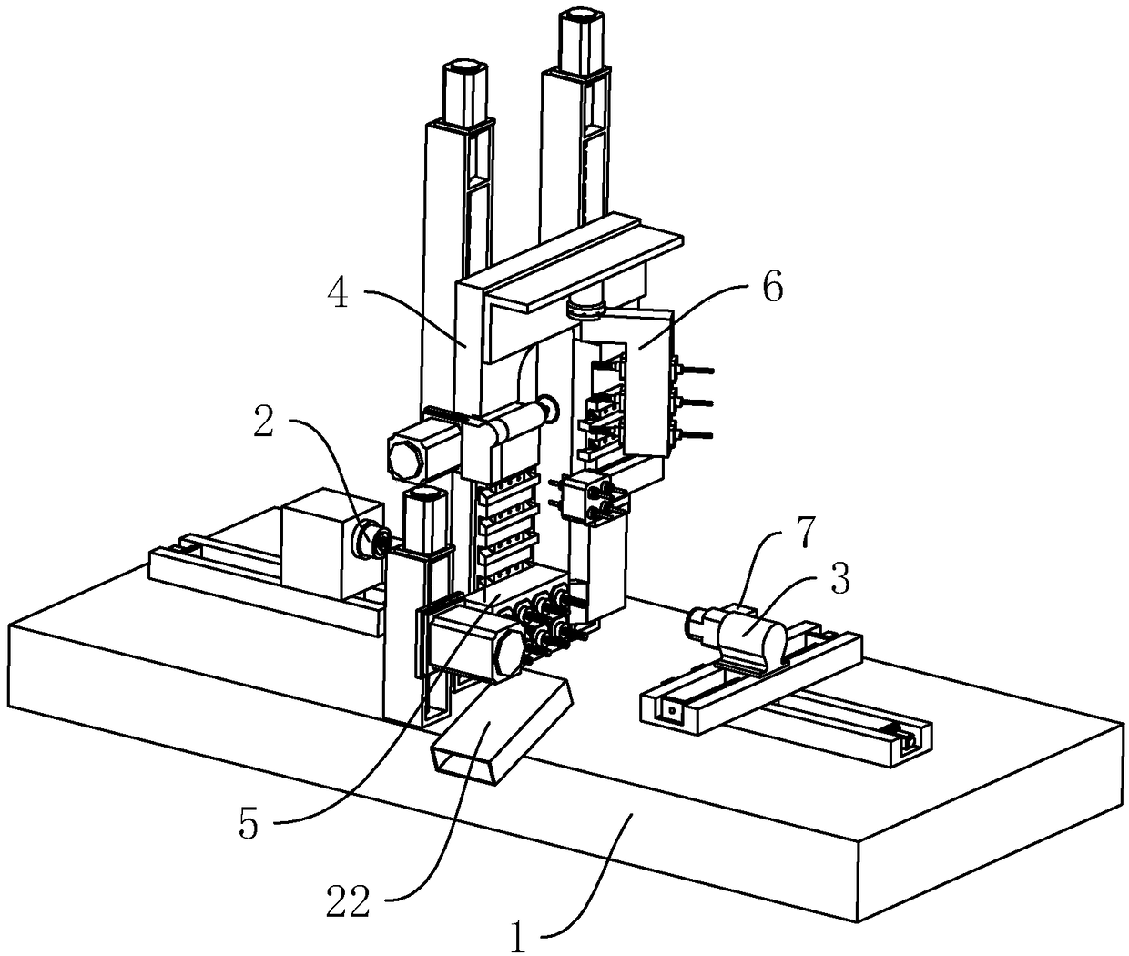
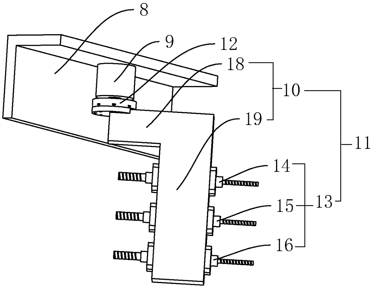
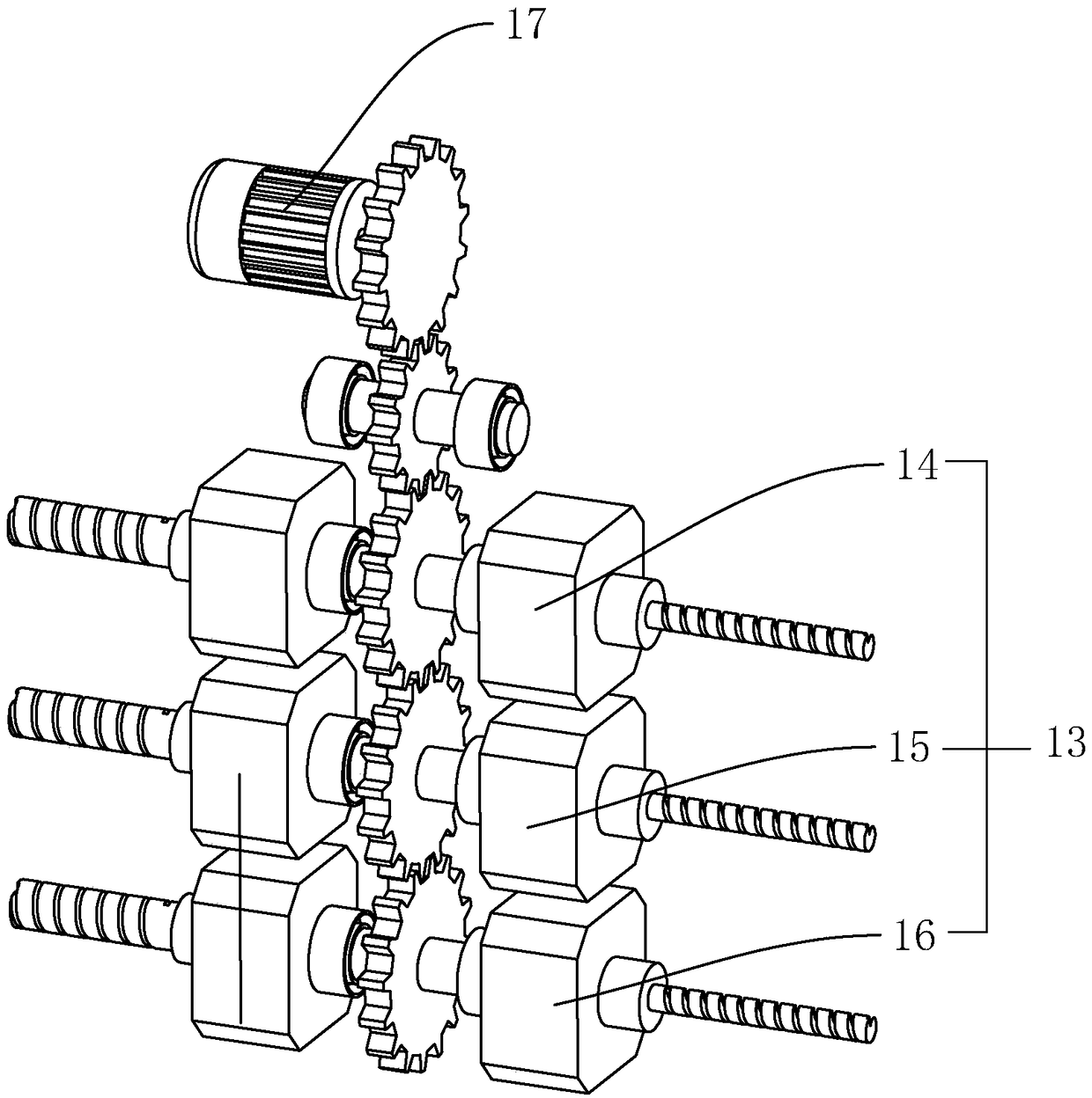
[0035] A continuous automatic lathe, such as figure 1 As shown in the figure, it includes a bed 1, a main shaft 2 that is slidably arranged on the bed 1 through the screw carriage, and a secondary shaft 3 that is slidably arranged on the bed 1 through the screw carriage, and will be set along the axial direction of the main shaft 2. It is the Z axis, which is set as the Y axis along the vertical direction, and the X axis along the horizontal direction and the direction perpendicular to the main shaft 2 is set as the X axis. The tool rest 4 with the axis sliding, the back tool rest 5 which is set on the bed 1 and moves up and down along the Y axis through the screw slide sliding seat, the main axis 2 can move along the Z axis, and the secondary axis 3 can move along the Z axis and X axis Moving, the tool holder 4 is provided with a B-axis mechanism 6 fo...


PUM


Abstract

The invention discloses an automatic machine tool with B-axis control, and relates to the technical field of machine tools. The automatic machine tool aims to solve the problems that a traditional machine tool cannot realize continuous machining when workpieces are obliquely machined, and time and labor are consumed when the angle is adjusted. According to the key points of the technical scheme, the automatic machine tool with the B-axis control comprises a lathe bed, a main shaft slidably arranged on the lathe bed along the Z axis, secondary shafts slidably arranged on the lathe bed along theZ axis and the X axis, a tool rest which is arranged on the lathe bed and can move along the X axis and the Y axis and a back tool platform which is arranged on the lathe bed and can move up and downalong the Y axis, wherein the tool rest is provided with a B-axis mechanism for obliquely machining a workpiece, and the secondary shafts are provided with deep hole assemblies for drilling deep holes in the end surface of the workpiece. The automatic machine tool with the B-axis control has the advantages of being capable of performing multi-angle oblique machining on the workpiece, realizing continuous machining of the workpiece, improving machining efficiency and reducing cost.

Description

technical field [0001] The invention relates to the technical field of machine tools, and more particularly, to an automatic machine tool with B-axis control. Background technique [0002] The application of machine tools in the field of precision machining is becoming more and more extensive. There are many methods for processing mechanical parts in modern machinery manufacturing: in addition to cutting, there are grinding, casting, forging, welding, stamping, extrusion, etc., but all the precision requirements are higher. Parts with high and fine surface roughness requirements generally need to be processed by cutting on the machine tool. [0003] The machine tool in the prior art usually has a main shaft, a secondary shaft and a tool holder. When processing a workpiece, usually only some simple processing can be performed, such as drilling a positive hole in the workpiece, and when it is necessary to punch an oblique hole in the workpiece. , it is necessary to manually a...

Claims


Application Information

Patent Timeline
Patent Type & Authority Applications(China)
IPC IPC(8): B23Q3/00B23Q5/10B23Q5/34B23Q16/02
CPCB23Q3/00B23Q5/10B23Q5/34B23Q16/02
Inventor 唐东雷
Owner 津上精密机床(浙江)有限公司
Learn More