
Clean energy power generation device

A power generation device and clean energy technology, applied in ocean energy power generation, engine components, machines/engines, etc., can solve difficult problems such as energy conversion and achieve efficient utilization

Active Publication Date: 2019-01-11
SHAANXI DATANG ENERGY SAVING TECH
View PDF5 Cites 4 Cited by
  • Summary
  • Abstract
  • Description
  • Claims
  • Application Information

AI Technical Summary

Problems solved by technology

However, since the impact of waves is carried out in two directions no matter whether it is high tide or low tide, it is difficult to convert the energy of these two directions

Method used


Image

  • Clean energy power generation device

Examples


Embodiment 1

[0031] like figure 1 shown:

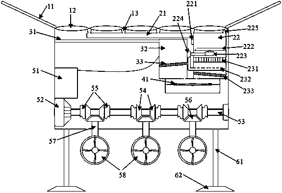
[0032] A clean energy power generation device includes a seawater desalination system, a rainwater collection and treatment system, a water supply system, a tidal energy power generation system and a support system.

[0033] The seawater desalination system includes a convex lens component, a condensate pipe and a condensate filter chamber.

[0034] The rainwater collection system includes solar panels, drains, rainwater collection pipes, bubble forming chambers and filter chambers.

[0035] The water supply system includes a water collecting and water outlet chamber.

[0036] The tidal energy power generation system includes a power storage room, a generator set, a main transmission shaft, a gear transmission component, a vertical transmission shaft and a water turbine.

[0037] The support system includes a support frame and an underwater base.

[0038]The solar panel is arranged on the top of the clean energy power generation device in the ...

Embodiment 2

[0051] A clean energy power generation device includes a seawater desalination system, a rainwater collection and treatment system, a water supply system, a tidal energy power generation system and a support system.

[0052] The seawater desalination system includes a convex lens component, a condensate pipe and a condensate filter chamber.

[0053] The rainwater collection system includes solar panels, drains, rainwater collection pipes, bubble forming chambers and filter chambers.

[0054] The water supply system includes a water collecting and water outlet chamber.

[0055] The tidal energy power generation system includes a power storage room, a generator set, a main transmission shaft, a gear transmission component, a vertical transmission shaft and a water turbine.

[0056] The support system includes a support frame and an underwater base.

[0057] The solar panel is arranged on the top of the clean energy power generation device in the form of a funnel, and a convex ...


PUM


Abstract

The invention relates to a clean energy power generation device. The clean energy power generation device comprises a seawater desalination system, a rainwater collection and treatment system, a watersupply system, a tidal energy power generation system and a supporting system. A plurality of clean energy power generation devices are arranged at the near-shore portions of water bodies such as anocean or a large-scale lake so that the water-body tidal energy and solar energy can be fully utilized; a convex lens component is arranged so that no matter sea water or lake water can achieve reinforced evaporation, and then condensation water storage or desalination can be achieved; the rainwater treatment system is arranged, the rainwater undergoes impurity removal and filtration, and then ismixed with condensed water to form clean water, so that water resource updating and utilization of the power generation device are realized; and a hydraulic turbine system is specifically arranged indetail so that the tidal energy can be more efficiently utilized.

Description

technical field [0001] The invention belongs to the field of new energy power generation, and in particular relates to a clean energy power generation device. Background technique [0002] The utilization of tidal energy is generally divided into two types. One is to build a dam on the shore of the water body, and a reservoir is built outside the dam to generate electricity through the height difference of the water body formed by the rising tide and the ebb tide; A device that can accept the impact of waves is set up in the center, by converting the kinetic energy of the waves into electrical energy. The second type can be divided into two forms. One is to set up a plate-like object by using the wave to move up and down, and the plate-like object moves up and down to generate electricity. Turbine to generate electricity. However, since the wave impact is carried out in two directions, whether it is high tide or low tide, it is difficult to convert the energy in both direc...

Claims


Application Information

Patent Timeline
Patent Type & Authority Applications(China)
IPC IPC(8): F03B13/26C02F9/10C02F103/08
CPCC02F1/001C02F1/14C02F1/24C02F1/50C02F9/00C02F2103/001C02F2103/08F03B13/26F05B2220/706Y02A20/144Y02E10/30
Inventor 张有明
Owner SHAANXI DATANG ENERGY SAVING TECH
Learn More