
Silo material stirring device

A stirring device and material technology, which is applied in the drying of solid materials, grain drying, drying gas arrangement, etc., can solve the problems of different compaction, uneven air supply, uneven ventilation and drying of grain moisture in the warehouse, etc., to shorten the drying time. time, the effect of improving drying efficiency

Pending Publication Date: 2019-01-11
合肥弘恩机电科技有限公司
View PDF0 Cites 1 Cited by
  • Summary
  • Abstract
  • Description
  • Claims
  • Application Information

AI Technical Summary

Problems solved by technology

[0002] In the grain storage drying system, after the high-moisture grains entering the silo are piled on the ventilation sieve plate at the bottom of the silo, the height of the grain pile in the silo is about 3-5m. Uniformity, resulting in different compaction at each point of the grain pile. When the dry air passes through the air distribution chamber at the bottom of the warehouse through the distributor and then passes along the gap in the grain pile under the action of the pressure difference of the fan, due to the difference in the density of the pile grain gap and the Due to the change of the air path ratio caused by the height difference of the grain pile, the ventilation air flow is short-circuited and the air supply to the grain pile is uneven.
As a result, the grain in the lower part of the grain pile in the warehouse dries quickly when ventilated, and the upper layer of the warehouse dries slowly, and the upper and lower grain layers have moisture stratification. The higher the grain pile, the more serious the stratification phenomenon, resulting in uneven ventilation and drying of the grain in the warehouse

Method used


Image

  • Silo material stirring device
  • Silo material stirring device
  • Silo material stirring device

Examples


Embodiment Construction

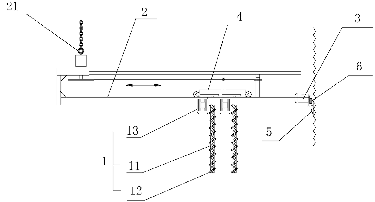
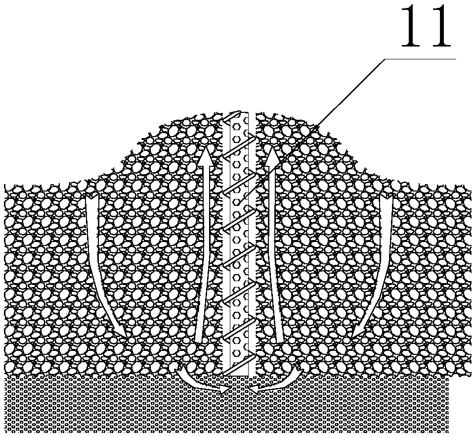
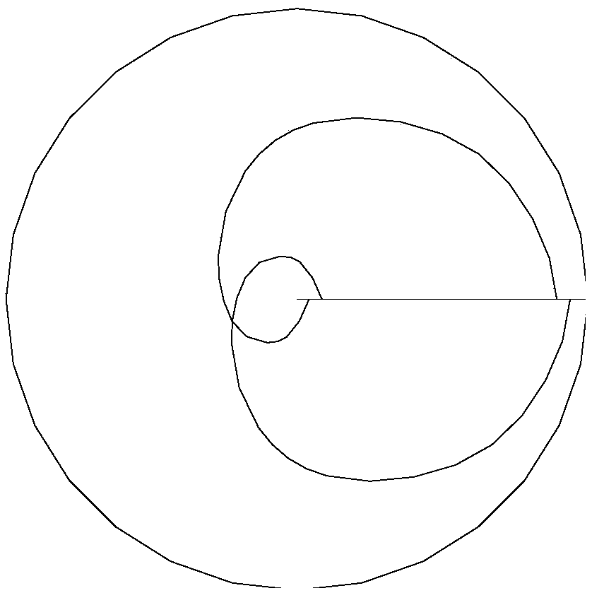
[0017] Such as Figure 1-5 as shown, figure 1 It is a structural schematic diagram of a material stirring device in a warehouse proposed by the present invention; figure 2 It is a schematic diagram of the stirrer turning over the material in the working state of the material stirring device in a warehouse proposed by the present invention; image 3 The movement track of the agitator in the material agitation device in the warehouse proposed by the present invention Figure 1 ; Figure 4 The movement track of the agitator in the material agitation device in the warehouse proposed by the present invention Figure II ; Figure 5 The movement track of the agitator in the material agitation device in the warehouse proposed by the present invention Figure three .

[0018] refer to Figure 1-2 , a material stirring device in a bin proposed by the present invention, comprising: a stirrer 1 and an air supply mechanism, wherein: the stirrer 1 includes a stirring shaft 11 for ve...


PUM


Abstract

The invention discloses a silo material stirring device. The silo material stirring device comprises a stirrer and an air feeding mechanism, wherein the stirrer comprises a stirring shaft, spiral blades and a power unit, wherein the stirring shaft is vertically inserted into a material silo; the spiral blades are mounted on the stirring shaft; and the power unit is used for driving the stirring shaft to rotate; a central cavity extending in the axial direction is formed in the stirring shaft; a plurality of air holes communicating with the central cavity are formed in the side wall of the stirring shaft; and the air feeding mechanism is movably connected with the stirring shaft to feed air into a central hole. According to the silo material stirring device, a problem of moisture gradient during drying materials in the silo is solved, the drying speed of the materials can be effectively increased while uniform drying and stable quality of the materials in the silo are realized, the drying time is shortened, and the drying efficiency is enhanced.

Description

technical field [0001] The invention relates to the technical field of material bin drying, in particular to a material stirring device in a bin. Background technique [0002] In the grain storage drying system, after the high-moisture grains entering the silo are piled on the ventilation sieve plate at the bottom of the silo, the height of the grain pile in the silo is about 3-5m. Uniformity, resulting in different compaction at each point of the grain pile. When the dry air passes through the air distribution chamber at the bottom of the warehouse through the distributor and then passes along the gap in the grain pile under the action of the pressure difference of the fan, due to the difference in the density of the pile grain gap and the Due to the change of the air path ratio caused by the height difference of the grain pile, the ventilation airflow is short-circuited and the air supply to the grain pile is uneven. As a result, the grain in the lower part of the grain p...

Claims


Application Information

Patent Timeline
IPC IPC(8): F26B11/12F26B21/00F26B25/04A23B9/08
CPCA23B9/08F26B11/12F26B21/004F26B25/04F26B2200/06
Inventor 周健程国红陈继圣何光文徐华贵王宇
Owner 合肥弘恩机电科技有限公司
Learn More