
Femtosecond laser machining parameter differential confocal Raman spectroscopy in-situ monitoring method and device

A femtosecond laser processing and differential confocal technology, which is used in measurement devices, Raman scattering, material excitation analysis, etc. Solve the problem of high-precision real-time fixed focus, realize online position monitoring and axial dimension detection, and improve the effect of controllability

Inactive Publication Date: 2019-01-11
BEIJING INSTITUTE OF TECHNOLOGYGY
View PDF10 Cites 6 Cited by
  • Summary
  • Abstract
  • Description
  • Claims
  • Application Information

AI Technical Summary

Problems solved by technology

[0010] The purpose of the present invention is to solve the problems of axial drift of samples in laser micro-nano processing and in-situ detection of complex shape and performance parameters of samples after processing. The present invention discloses a femtosecond laser processing parameter differential confocal Raman The spectroscopic in-situ monitoring method and device realize the on-line monitoring of axial drift and inclination during sample processing and nanoscale monitoring of the axial size of the sample structure, ensuring accurate real-time focusing of the sample during processing, and realizing processing After the completion of the comprehensive detection of the micro-region morphology and complex physical parameters of the sample, it provides a technical basis for the feedback correction, mechanism research and process improvement of femtosecond laser processing, and improves the controllability of laser processing accuracy and the processing quality of samples.

Method used


Image

  • Femtosecond laser machining parameter differential confocal Raman spectroscopy in-situ monitoring method and device
  • Femtosecond laser machining parameter differential confocal Raman spectroscopy in-situ monitoring method and device
  • Femtosecond laser machining parameter differential confocal Raman spectroscopy in-situ monitoring method and device

Examples


Embodiment 1

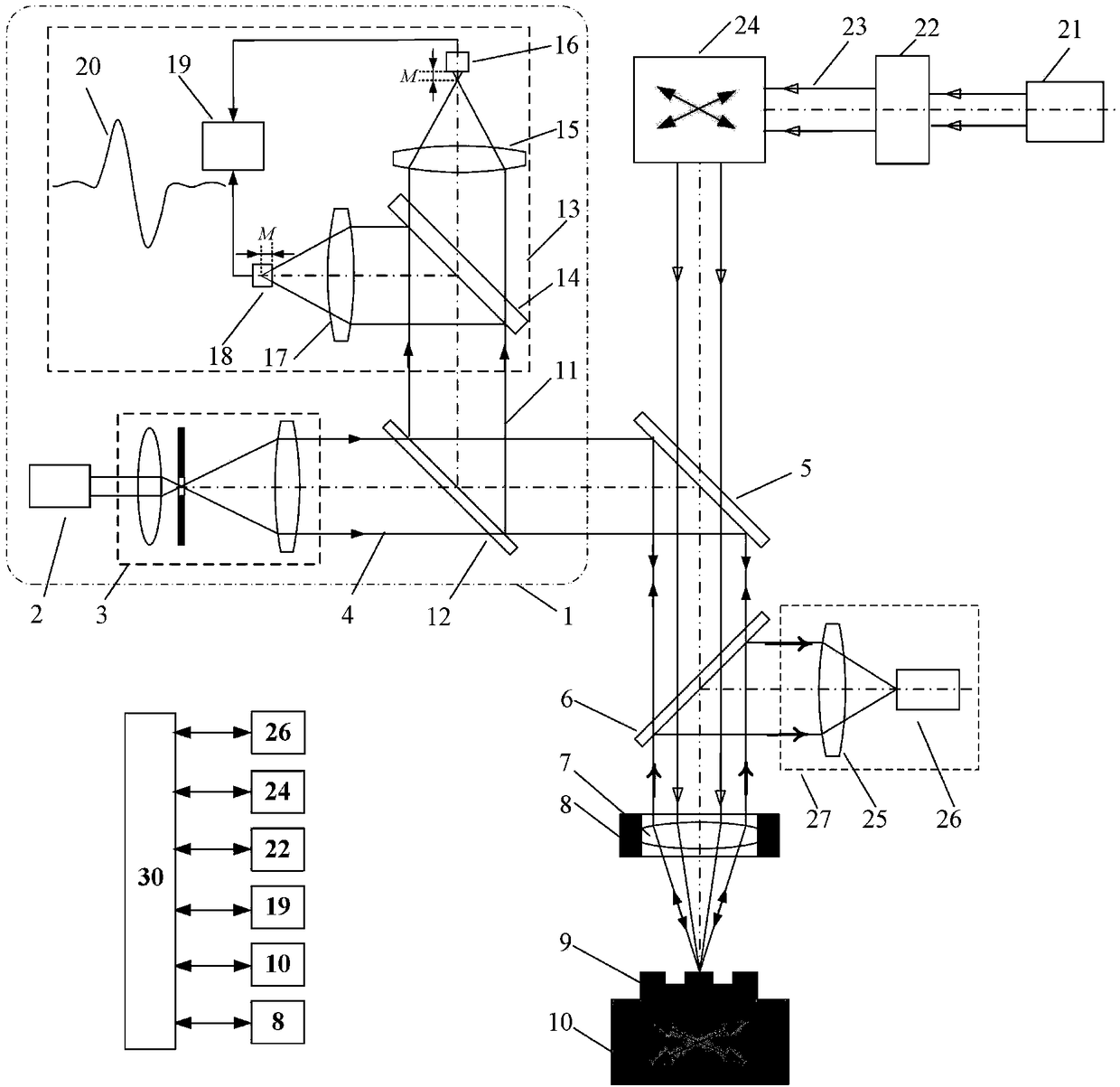
[0047] Such as figure 1 As shown, the computer 30 performs feedback control on the two-dimensional scanner 18, the precision workbench 10, and the axial scanner 8 to realize three-dimensional scanning and position adjustment of the processing and monitoring of the sample 9; the femtosecond laser processing system consists of a femtosecond laser 21 , laser spatiotemporal shaping module 22, two-dimensional scanner 18; 18 and a differential processing module 19; and the first intensity detector 16 and the second intensity detector 18 deviate from the focal planes of the first detection objective lens 15 and the second detection objective lens 17 at equal distances but in opposite directions.

[0048] The implementation steps of the femtosecond laser processing parameter differential confocal Raman spectroscopy in-situ monitoring method are as follows:

[0049] 1) Place the sample 9 on the precision workbench 10, and the precision workbench 10 drives the sample 9 to perform scann...

Embodiment 2

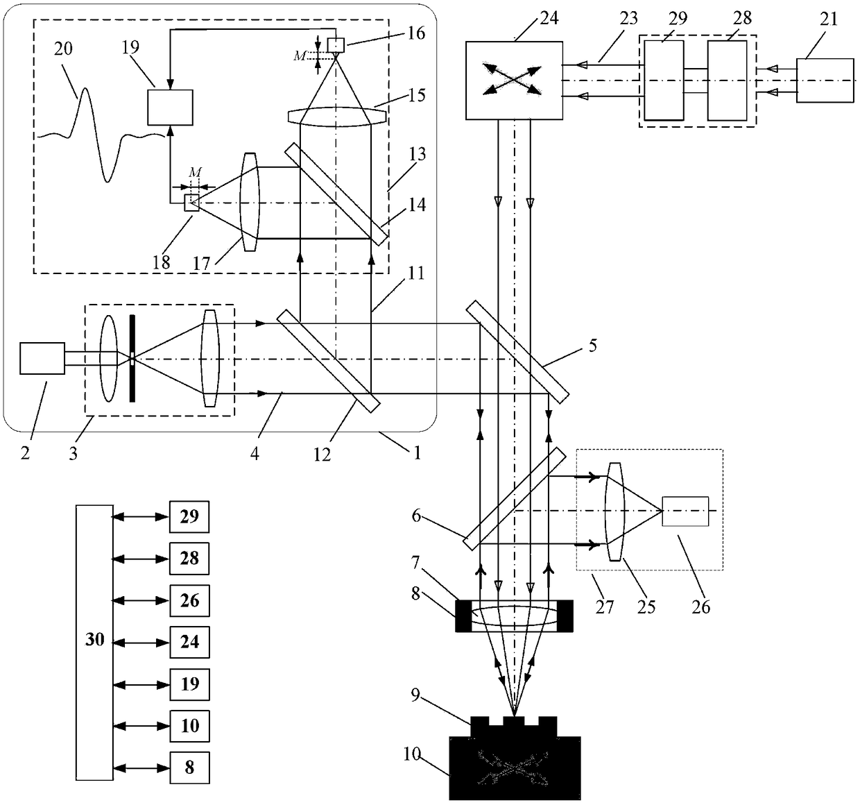
[0058] Such as figure 2 As shown, the laser space-time shaping module 22 is composed of a space shaper 28 and a time shaper 29, and adjusts the time-domain and space-domain parameters of the light beam emitted by the femtosecond laser 21, so as to optimize the femtosecond laser processing performance.

[0059] All the other are identical with embodiment 1.

Embodiment 3

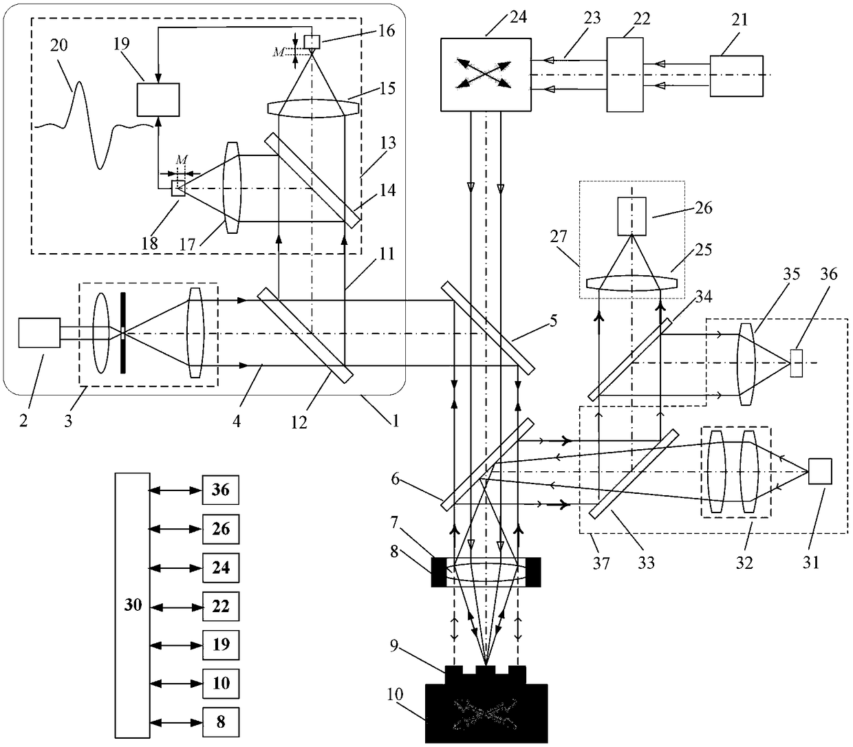
[0061] Such as image 3 As shown, before processing, after the sample 9 is placed on the precision workbench 10, the sample 9 is roughly aligned using the microscopic imaging module 37, and the light emitted by the white light source 31 passes through the illumination system 32, the illumination beam splitter 33, and the dichroic After the color mirror B 6 and the objective lens 7, parallel light beams are generated to uniformly irradiate the sample 9, and the illumination light reflected by the sample 9 is reflected by the illumination beam splitter 33 and the second beam splitter 34 and then imaged on the CCD 36 by the imaging objective lens 35, and the sample 9 can be obtained. The position and imaging area of ​​the sample 9 can be determined, and the tilt and position of the sample 9 can be judged.

[0062] All the other are identical with embodiment 1.


PUM


Abstract

The invention relates to a femtosecond laser machining parameter differential confocal Raman spectroscopy in-situ monitoring method and device, and belongs to the fields of a laser precision detectiontechnology and a femtosecond laser machining and manufacturing technology. A laser differential confocal axial monitoring module with high axial resolution and a femtosecond laser machining system are organically fused, and the axial position of a sample is subjected to nano-scale monitoring and sample axial machining size measurement by utilizing a curve zero point of a differential confocal system, so that the real-time focus fixing of the axial position of the sample and the high-precision measurement of the size of a micro-nano structure after machining are realized, and the drift problemand the high-precision online detection problem in the measurement process are solved; and a differential confocal Raman spectroscopy detection module is used for carrying out monitoring analysis oninformation such as the molecular structure and the like of a sample material after femtosecond laser machining, and the information is fused through a computer, so that the high-precision femtosecondlaser machining of a micro-structure and the in-situ monitoring analysis of the morphology performance of a micro-region are integrated, and the controllability of the femtosecond laser machining precision of the micro-structure, the machining quality of the sample and the like are improved.

Description

technical field [0001] The invention relates to a method and device for in-situ monitoring of femtosecond laser processing parameters by differential confocal Raman spectroscopy, which belongs to the field of laser precision detection technology and femtosecond laser processing and manufacturing technology, and can be used for in-situ femtosecond laser processing micro-area morphology and performance of fine structures Online monitoring and analysis. Background technique [0002] Femtosecond laser processing is regarded as a century-old technology that "may cause a new industrial revolution" due to its remarkable advantages such as wide material adaptability, high processing precision, and no mask required, and is regarded as a macro-micro-spanning technology. The preferred method of scale micro-nano manufacturing has been given priority in the development of China, the United States and other major manufacturing countries in the world. [0003] Femtosecond laser processing...

Claims


Application Information

Patent Timeline
IPC IPC(8): G01N21/65G01N21/01
Inventor 赵维谦邱丽荣王允
Owner BEIJING INSTITUTE OF TECHNOLOGYGY
Learn More