Method for generating two-dimensional identical-focal spot array by using radiation field of planar array antenna

A planar antenna and radiation field technology, applied in the direction of optical components, optics, instruments, etc., can solve the problems of not achieving the best effect, uneven intensity distribution of focal spots, difficult control of the number and position of focal spots, etc. control effect

Active Publication Date: 2019-01-11
QUANZHOU NORMAL UNIV
View PDF3 Cites 9 Cited by
  • Summary
  • Abstract
  • Description
  • Claims
  • Application Information

AI Technical Summary

Problems solved by technology

[0004] The methods reported above usually require optimal design of optical components, which leads to suboptimal results
In addition, the intensity distribution of focal spots in the array produced by the above method is not uniform enough, and the number and position of focal spots are not easy to control

Method used


Image

  • Method for generating two-dimensional identical-focal spot array by using radiation field of planar array antenna
  • Method for generating two-dimensional identical-focal spot array by using radiation field of planar array antenna
  • Method for generating two-dimensional identical-focal spot array by using radiation field of planar array antenna

Examples


Embodiment 1

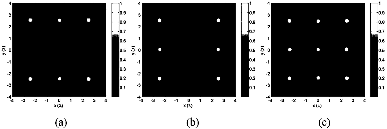
[0067] Coefficient C 0 And C 1 Since it has nothing to do with the focal spot shape in the array, it is normalized to 1 for simplicity. The field radiated from the antenna array should be completely collected and collimated to the pupil surface for the construction of the focal spot array. Therefore, the maximum radiation angle of the lens is set to θ max =π / 2, the corresponding numerical aperture NA=1, this value can be achieved by using a reflective lens or a hyperplane lens. Here are four different types of specific focal spot arrays to demonstrate the simplicity and flexibility of the proposed method. It consists of 2×3, 3×2, 3×3 array elements, separated by d x =2.5λ and d y =5.0λ, d x =5.0λ and d y =2.5λ, d x =2.5λ and d y =2.5λ, the radiation field of the arranged rectangular dipole array (including the square array) is used to generate a two-dimensional array of the same focal spot, such as figure 2 Shown. From figure 2 It can be clearly seen that the focal spots on ...

Embodiment 2

[0069] If five dipole antennas are arranged diagonally, the interval is d x =1.5λ and d y =1.5λ, with its radiation pattern, a diagonal focal spot array can be easily generated on the XY focal plane, such as image 3 Shown. Similarly, the intensity of each focal spot is the same, and its center position can be adjusted by adjusting the parameter d x And d y To customize. image 3 Among them, (a) is the right diagonal focal spot array, (b) is the left diagonal focal spot array, and (c) is the V-shaped focal spot array.

Embodiment 3

[0071] Figure 4 Shown are regular pentagon, regular hexagon, and regular octagonal focal spot arrays. These regular polygon focal spot distributions are easily realized by using the radiation field of an antenna array with regular pentagon, regular hexagon and regular octagonal arrangement. Obviously, this method can also be used to generate other polygonal focal spot arrays. This shows that the required polygonal focal spot array can be obtained by inverting the radiation field of the corresponding polygonal dipole array, and the center position of each focal spot on the XY focal plane can be adjusted by adjusting the coordinates of the corresponding dipole array element To manipulate. Figure 4 Among them, (a) is a regular pentagonal focal spot array, (b) is a regular hexagonal focal spot array, and (c) is a regular octagonal focal spot array.


PUM


Abstract

The invention relates to a method for generating a two-dimensional identical-focal spot array by using the radiation field of a planar array antenna. The method comprises the steps of firstly adoptinga 4[pai] focusing system composed of two high numerical aperture lenses; then arranging a virtual planar antenna array in the center of the focal plane of the 4[pai] focusing system composed of the two high numerical aperture lenses, wherein the electromagnetic field radiated by the antenna array is outwards propagated to the lens on the image space side, and completely collected by the two highnumerical aperture lenses, and then continuously propagated to the pupil planes of the two lenses, and thus field distribution on the pupil planes is achieved; and at last, regarding the field distribution on the pupil planes to be incident fields and reversely transmitting the incident fields to a focal region, so as to generate the two-dimensional identical-focal spot array with specific characteristics on the focal plane of the high numerical aperture lenses. According to the method provided by the invention, the two-dimensional identical-focal spot array having the specific quantity, separation distances and positions is generated by using the method with no need to optimize.

Description

Technical field [0001] The invention relates to the technical field of generating a two-dimensional focal spot array, in particular to a method for generating a two-dimensional identical focal spot array by using the radiation field of a planar antenna array. Background technique [0002] The sub-wavelength focal spot produced by the tight focus of a high numerical aperture (NA) lens has been extensively studied because it has important applications in optical microscopy, optical tweezers, photon capture and manipulation, and single-molecule fluorescence spectroscopy. In addition, in certain special occasions of parallel and synchronous processing, a two-dimensional focal spot array with controllable characteristics is required. Therefore, many methods of creating two-dimensional focal spot arrays have been proposed. [0003] In 2000, D. Fittinghoff et al. proposed the use of cascaded beam splitters to generate an 8×2 time-independent focal spot array. In 2011, H.Guo et al. used ...

Claims


Application Information

Patent Timeline
Patent Type & Authority Applications(China)
IPC IPC(8): G02B27/00
CPCG02B27/0012
Inventor 余燕忠储贻波
Owner QUANZHOU NORMAL UNIV
Why Eureka
Try Eureka