Optical fiber combination-based numerical control phase-modulated light source device and method

A technology of phase modulation and optical fiber combining, which is applied in the field of optics, can solve the problems that laser correlation imaging is difficult to achieve real-time imaging effect, limit the imaging distance of laser correlation imaging system, and limit the sampling rate of imaging system, so as to improve energy utilization rate and energy efficiency. Low loss, improved imaging and detection distance effect

Inactive Publication Date: 2019-01-11
THE GENERAL DESIGNING INST OF HUBEI SPACE TECH ACAD
View PDF4 Cites 1 Cited by
  • Summary
  • Abstract
  • Description
  • Claims
  • Application Information

AI Technical Summary

Problems solved by technology

[0004] The modulated illumination source used in laser correlation imaging is mainly obtained by irradiating the ground glass with laser. The purpose of laser irradiating the ground glass is to make the phase modulation of different cell positions of the ground glass in the laser spot, and the modulation amplitude is completely random. The light intensity of a point is obtained by the coherence of laser beams passing through different cells in the laser spot. This method of light source is relatively simple and stable, and is suitable for the theoretical research of laser correlation imaging, but it also has the problem of low energy utilization. See figure 1 As shown, it is mainly composed of pulse laser a, frosted glass b, beam splitter c, lens d, mirror e, area array CCD f, etc., in which the ground glass b is placed on the motor, including a translational and a rotating motor. During the use of the device, the motor makes the ground glass b perform reciprocating spiral motion, so that the speckle field after each laser pulse passes through the ground glass b is irrelevant, and the laser speckle field emitted after the ground glass b is divided into two paths by the beam splitter c, One of them passes through the imaging system and is received by the area detector CCD f to record the energy distribution in each speckle field, and the other one passes through a lens d and then exits, forming a traditional light source device as a whole
Since the scattering angle θ distribution angle of the laser light after passing through the ground glass b is 180°, and the laser divergence angle that can be coupled into the subsequent optical system is γ, its value is generally less than 5°, resulting in low energy utilization in traditional light source devices, generally 1 %, the maximum is no more than 5%, which limits the imaging distance of the laser correlation imaging system
And behind the beam splitter c, an area array CCD f is used. Generally, the existing area array CCD image acquisition frame rate is low, which is lower than 2kHz in the case of full scale, so the pulse frequency of the traditional light source device is up to 2kHz.
[0005] In addition, due to the fixed distribution of particles on the ground glass surface, when it is necessary to change the laser phase modulation state, it is necessary to rotate the ground glass so that the laser irradiation area is different to obtain a new speckle field. This mechanical rotation also limits the sampling rate of the imaging system, making Laser correlation imaging is difficult to achieve real-time imaging effects. Therefore, the laser correlation imaging system encounters challenges in the engineering process

Method used


Image

  • Optical fiber combination-based numerical control phase-modulated light source device and method
  • Optical fiber combination-based numerical control phase-modulated light source device and method
  • Optical fiber combination-based numerical control phase-modulated light source device and method

Examples


Embodiment Construction

[0037] The present invention will be described in further detail below in conjunction with the accompanying drawings and embodiments.

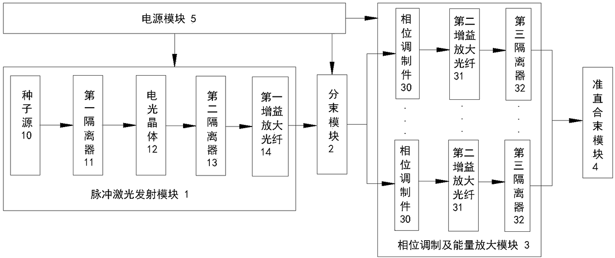
[0038] see figure 2 As shown, the embodiment of the present invention provides a digitally controlled phase modulation light source device based on optical fiber beam combining, which includes a pulsed laser emitting module 1, a beam splitting module 2, a phase modulation and energy amplification module 3, and a collimating beam combining module 4; in,

[0039] The pulse laser emitting module 1 is used to emit the first pulse laser to the beam splitting module 2;

[0040] The beam splitting module 2 includes an optical fiber beam splitter, such as a single-mode optical fiber beam splitter, for dividing the received first pulsed laser into N beams of second pulsed lasers, and the N beams of second pulsed lasers are transmitted to the phase modulation And energy amplification module 3, N≥4;

[0041] The phase modulation and energy amplificat...


PUM


Abstract

The invention discloses an optical fiber combination-based numerical control phase-modulated light source device and a method. The light source device comprises a pulse laser emission module, a beam splitting module, a phase modulation and energy amplification module and a collimation and combination module, wherein the pulse laser emission module is used for emitting first pulse laser to the beamsplitting module; the beam splitting module is used for splitting the received first pulse beam into N beams of second pulse laser, and the N beams of second pulse laser are transmitted to the phasemodulation and energy amplification module through an optical fiber, N being more than or equal to 4; the phase modulation and energy amplification module is used for performing phase modulation and pulse energy amplification on each beam of second pulse laser to obtain N beams of third pulse laser; and the collimation and combination module is used for combining the N beams of third pulse laser to make the N beams of third pulse laser intersected and interfere on a conjugate surface to obtain a speckle field. According to the device and the method, the energy utilization rate is high, the imaging and detection distance is prolonged, and the repetition frequency of a laser pulse is increased to increase the imaging frame frequency of a laser correlated imaging system.

Description

technical field [0001] The invention relates to the field of optical technology, in particular to a digitally controlled phase modulation light source device and method based on fiber combining. Background technique [0002] Different from the traditional point-to-point imaging mechanism, laser correlation imaging mainly uses a single-pixel detector to detect the light intensity passing through the object or reflected from the surface of the object, and correlates it with the light intensity detected by the reference arm to obtain the object The image, which is a typical nonlocal imaging technology, has become a hot research direction in the field of quantum optics in the past 10 years. It has broad application prospects in the fields of remote sensing, medical imaging and X-ray imaging. [0003] Laser correlation imaging is a non-local imaging method. Its object is in the object arm, and the reference arm does not contain objects, so its detection and imaging are separated...

Claims


Application Information

Patent Timeline
Patent Type & Authority Applications(China)
IPC IPC(8): G02F1/03G02F1/095G02F1/125
CPCG02F1/03G02F1/0955G02F1/125
Inventor 徐旭阳史要涛周一帆张燕柯才军于翠萍庞宏俊
Owner THE GENERAL DESIGNING INST OF HUBEI SPACE TECH ACAD
Why Eureka
Try Eureka