
Design method of approximate flat-topped main beam for microwave wireless energy transmission system

A technology of energy transmission and microwave wireless, which is applied in radio transmission systems, transmission systems, diversity/multi-antenna systems, etc., and can solve problems such as low efficiency

Active Publication Date: 2019-01-11
XIDIAN UNIV
View PDF3 Cites 4 Cited by
  • Summary
  • Abstract
  • Description
  • Claims
  • Application Information

AI Technical Summary

Problems solved by technology

[0010] However, in these researches, there is a problem of inefficiency in the way of using the optimization method to obtain the flat-top main beam, and it is all for short-distance transmission. For microwave wireless energy transmission of space solar power plants, it is long-distance transmission and transmission efficiency is crucial

Method used

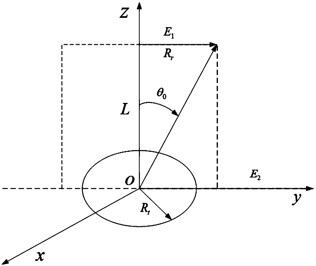
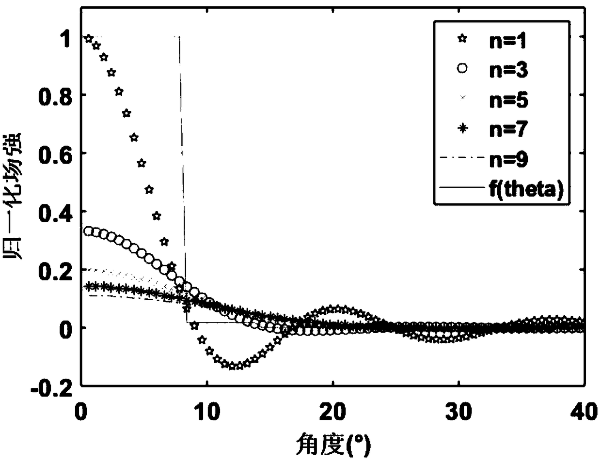
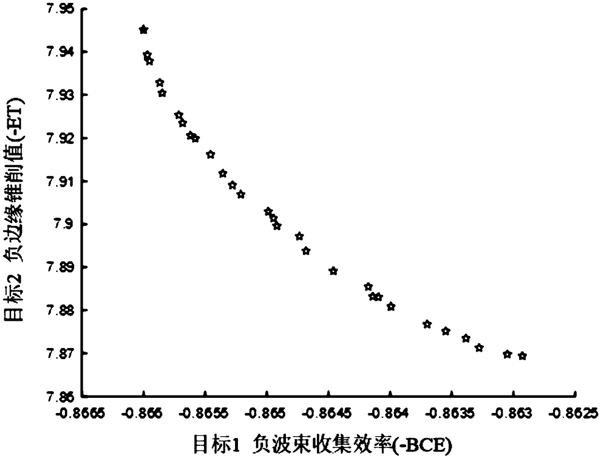

Image

  • Design method of approximate flat-topped main beam for microwave wireless energy transmission system
  • Design method of approximate flat-topped main beam for microwave wireless energy transmission system
  • Design method of approximate flat-topped main beam for microwave wireless energy transmission system

Examples


Embodiment Construction

[0095] Specific embodiments of the present invention will be described in detail below.

[0096] A method for designing an approximate flat-top main beam for a microwave wireless energy transfer system, including:

[0097] (1) Calculate the basic field strength pattern at the far field of the transmitting antenna according to the aperture field distribution function

[0098] Define the aperture field distribution of the transmitting antenna as

[0099] f(ρ)=[1-(ρ) 2 ] n-1 , 0≤ρ≤1 (1)

[0100] in:

[0101] (n-1) represents the rule that the aperture field decreases along the radial direction, n=1,2,3,...,N, N is a positive integer greater than or equal to 1, when n=1, it indicates that the aperture field adopts a uniform distribution;

[0102] ρ is the normalized radius of the transmitting antenna;

[0103] Then the basic field strength pattern E at the far field of the transmitting antenna can be obtained n (θ), whose expression is

[0104]

[0105] in:

[0106] j ...


PUM


Abstract

The invention relates to a design method of an approximate flat-top main beam for a microwave wireless energy transmission system. The method comprises the following steps: (1) calculating a basic field strength pattern at a far field of a transmitting antenna according to an aperture field distribution function; (2) constructing the flat-top main beam field intensity pattern function Eflat-top(theta); (3) defining the description function of the flat-topped main beam and determining the objective function of the least square curve fitting; (4) using the least square method, and obtaining thefield intensity pattern function Eflat-top(theta); (5) calculating beam collection efficiency and edge coning on the receiving antenna; (6) using the following optimization model to optimize the objective function to obtain the optimal beam collection efficiency and the optimal coning value of the receiving antenna edge; (7) obtaining a design variable X; (8) according to the design variable X andthe Pareto front-end diagram, obtaining the optimal beam collection efficiency and the coning value of the receiving antenna edge as well as the flat-top main beam field intensity pattern function Eflat-top(theta).

Description

technical field [0001] The invention belongs to the technical field of antennas, and in particular relates to a design method for an approximate flat-top main beam of a microwave wireless energy transmission system, which can be used to realize the array integration of an active phased array transmitting antenna and the energy on the receiving antenna in a microwave wireless energy transmission system an approximately uniform distribution. Background technique [0002] Space solar power plant is a new type of green energy system that collects solar energy in space, converts solar energy into electrical energy, and then transmits electrical energy to the ground in the form of microwaves through transmitting antennas. [0003] As one of the key components of space solar power plants, Microwave Wireless Power Transmission (MPT) has other broad application prospects. Such as wireless energy transmission for drones, airships, etc., and flexible power supply for disaster areas an...

Claims


Application Information

Patent Timeline
IPC IPC(8): G06F17/50H04B7/0408H04B7/06
CPCH04B7/0408H04B7/06G06F30/20
Inventor 宋立伟刘永磊姚毅鲁斯斯史婷婷黄松然
Owner XIDIAN UNIV
Learn More