A PVC insulating cable

An insulated cable, polyvinyl chloride technology, applied in insulated cables, insulated conductors, organic insulators, etc., can solve the problems of affecting the signal transmission of power core conductors, affecting the service life of the cable body, and not being able to protect the cable body. The effect of large-scale production and use, increasing signal interference ability and wide range of use

Inactive Publication Date: 2019-01-11
台山市电缆厂有限责任公司
View PDF6 Cites 2 Cited by
  • Summary
  • Abstract
  • Description
  • Claims
  • Application Information

AI Technical Summary

Problems solved by technology

[0003] A Chinese patent discloses an overhead insulated cable. (Authorized announcement number CN201877195U). This patented technology can be bundled together with multiple single-core overhead insulated cables to play the role of fixing and suspension. The structure is stable and the operation is safe and reliable. The application saves space and is easy to lay. The conductor of the cable can use a copper core (or hard copper core, aluminum core, aluminum alloy core) with a large cross-section conductor with a large transmission capacity. However, the cables currently on the market do not have a pulling mechanism, which is inconvenient. The staff uses the pulling mechanism to pull the position of the cable body, which cannot prevent the user from directly contacting the cable body. Because the working environment of the cable body is relatively harsh, in the cold winter, the cable body may freeze and crack, which affects the quality of the cable body. In addition, the cable body is susceptible to signal interference in the external environment, which affects the signal transmission of the power core conductor in the cable body. Without a heat-shrinkable outer sheath, the cable body cannot be protected, which in turn affects the cable body. Without a flame retardant layer, it cannot avoid the phenomenon of burning of the power core conductor inside the cable body due to high heat

Method used


Image

  • A PVC insulating cable
  • A PVC insulating cable
  • A PVC insulating cable

Examples


Embodiment Construction

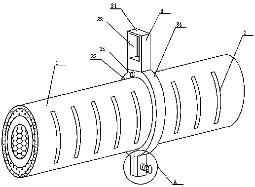
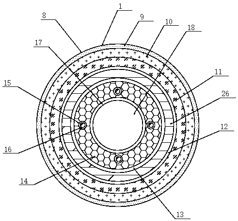
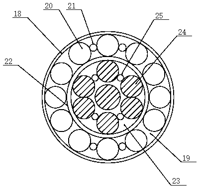
[0023] see Figure 1~5 , in an embodiment of the present invention, a polyvinyl chloride insulated cable includes a cable body 1 and a pulling mechanism 3, the surface of the cable body 1 is provided with anti-slip stripes 2, and the outside of the cable body 1 is equipped with a pulling mechanism 3, the cable body 1 A power line core conductor 24 is arranged near the center of the inside of the power line core conductor 24, and the power line core conductor 24 is surrounded by a first water blocking layer 22, and one side of the power line core conductor 24 is provided with The first water blocking yarn layer 25, and the surface of the first water blocking tape layer 22 is coated with a graphene layer, the thickness of the graphene layer is 0.2 nm to 0.4 nm, and the inside of the first water blocking tape layer 22 is filled with the first Filling layer 23, and the outside of the first water blocking belt layer 22 is wrapped with the second water blocking belt layer 18, the in...


PUM

PropertyMeasurementUnit
thicknessaaaaaaaaaa
thicknessaaaaaaaaaa
thicknessaaaaaaaaaa

Abstract

A PVC insulating cable disclosed in the invention comprises a cable body and a pulling mechanism, wherein the surface of the cable body is provided with an anti-slip stripe, and the outer part of thecable body is provided with a pulling mechanism, the inner part of the cable body is provided with a power wire core conductor near a center position, the power wire core conductor is arranged aroundthe cable body, and the outer part of the power wire core conductor is wrapped with a first water stop layer. A pull mechanism is provided, the invention is convenient for the worker to pull the position of the cable body by using a pulling mechanism, heat preservation layer is provided, the phenomenon of freezing and cracking on the cable body is avoided, a shield hollow layer, a shielding particle fil layer, a hollow straight column and a shielding liquid adsorbing cotton layer are arrange, that signal interference ability of the cable body is increased, a heat shrinkable outer protective layer is arranged, the cable body can be protected, a flame retardant layer is arranged, and the phenomenon that combustion occurs due to high heat of the power wire core conductor inside the cable bodycan be avoided.

Description

technical field [0001] The invention relates to the technical field of cables, in particular to a polyvinyl chloride insulated cable. Background technique [0002] The cable is usually a rope-like cable twisted by several or groups of wires [at least two in each group]. Each group of wires is insulated from each other and is often twisted around a center. The insulating covering layer is mostly erected in the air or installed underground or underwater for telecommunications or power transmission. The cable is mainly composed of the following 4 parts. Conductive core: made of high conductivity material (copper or aluminum), according to the laying The use conditions require the softness of the cable. Each core may be twisted from a single wire or multiple wires; insulation layer: the insulation material used for the cable should have high insulation resistance, high breakdown electric field strength, Low dielectric loss and low dielectric constant. Commonly used insulating m...

Claims


Application Information

Patent Timeline
Patent Type & Authority Applications(China)
IPC IPC(8): H01B7/02H01B7/28H01B7/282H01B7/29H01B7/295H01B9/02H01B3/44
CPCH01B7/295H01B3/443H01B7/02H01B7/28H01B7/282H01B7/29H01B9/02
Inventor 张毅良
Owner 台山市电缆厂有限责任公司
Why Eureka
Try Eureka