A Space Laser Communication Launcher

A laser communication and emission device technology, which is applied in the direction of electromagnetic transmitters, electrical components, electromagnetic wave transmission systems, etc., can solve the problems of increased bandwidth of optical filters at the receiving end, low energy utilization efficiency, and high system complexity, so as to improve the emission of light. Power, saving optical bandwidth resources, and flexible application scenarios

Active Publication Date: 2020-08-18
THE GENERAL DESIGNING INST OF HUBEI SPACE TECH ACAD
View PDF8 Cites 0 Cited by
  • Summary
  • Abstract
  • Description
  • Claims
  • Application Information

AI Technical Summary

Problems solved by technology

Generally, the saturated output power of SOA, which is suitable for communication, is relatively small compared with high-power EDFA. In the application of long-distance space laser communication, it is difficult to meet the satisfactory output optical power requirements.
[0004] At present, in order to increase the output power of single-wavelength signal light, on the one hand, the method of spatially coupling and superimposing multiple laser sources can be adopted, but this method makes the system more complex and the energy utilization efficiency is lower; on the other hand, if using Signal light sources of different wavelengths are combined according to the wavelength, which will cause a serious waste of optical bandwidth resources, and increase the bandwidth of the optical filter at the receiving end, thereby introducing more background stray light
Therefore, for the communication wavelengths corresponding to the lack of effective high-power optical amplifiers, there is still a lack of simple, effective and reliable means when increasing the signal light output power of the space laser communication system

Method used


Image

  • A Space Laser Communication Launcher
  • A Space Laser Communication Launcher

Examples


Embodiment Construction

[0035] Embodiments of the present invention will be described in further detail below in conjunction with the accompanying drawings.

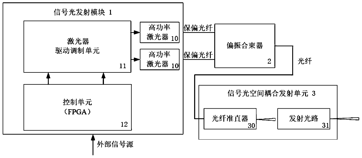
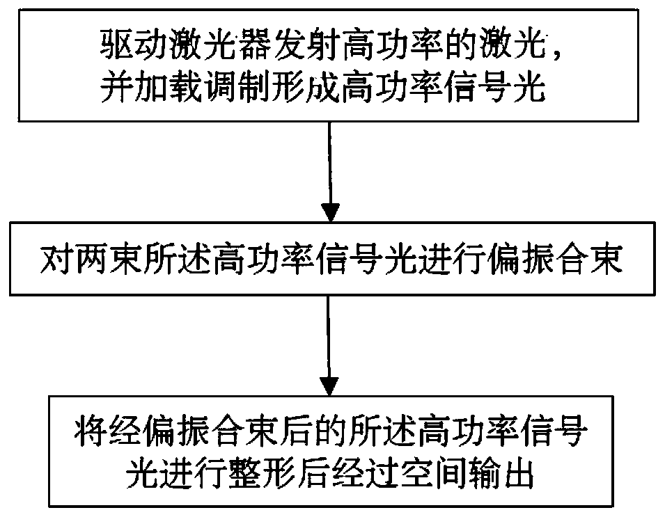
[0036] see figure 1 As shown, the embodiment of the present invention provides a space laser communication transmitting device, including a signal light transmitting module 1, and the signal light transmitting module 1 is mainly used to generate high-power signal light. Specifically, the signal light transmitting module 1 includes a laser drive modulation unit 11 and two high-power lasers 10, wherein the laser drive modulation unit 11 is used to drive the two high-power lasers 10 to generate high-power lasers, and the high-power lasers are loaded with modulation signals , generating high-power signal light.

[0037] The laser drive modulation unit 11 includes two laser drive modulation circuits, the two laser drive modulation circuits respectively drive and modulate the two high-power lasers 10, and the modulation signals of the two laser driv...


PUM

PropertyMeasurementUnit
wavelengthaaaaaaaaaa

Abstract

The present invention discloses a laser space communication emission device, and relates to the field of laser space communication. The device comprises a signal optical emission module, a polarization beam combiner and a signal optical space coupling emission unit. The signal optical emission module comprises a laser drive modulation unit and two high-power lasers, the laser drive modulation unitis configured to drive the high-power lasers to generate high power lasers, the high power lasers are loaded and modulated to form high-power signal light, the polarization beam combiner is configured to perform polarization beam combination of the two received high-power signal light, and the signal optical space coupling emission unit is configured to perform beam shaping of the high-power signal light after polarization beam combination and perform output of the high-power signal light through a space. The laser space communication emission device can achieve high-power and high-reliability signal light emission in a condition without depending on an optical amplifier, and is simple in device structure, high in reliability, flexible in application mode and wide in application range.

Description

technical field [0001] The invention relates to the field of space laser communication, in particular to a space laser communication transmitting device. Background technique [0002] In the space laser communication system, the laser output optical power is one of the key parameters affecting the communication distance and system performance. In order to obtain a larger communication distance and better anti-noise performance, it is necessary to increase the output signal optical power of the system. [0003] In order to obtain a high-power laser signal light source, the method of modulating the signal of the laser seed light source is generally used and then amplified, but the current mature commercial communication optical amplifier solution is the erbium-doped fiber amplifier EDFA for C_band or L_band, and for other bands such as In the 800nm ​​band, there is no high-power output optical amplifier particularly suitable for communication. Generally, the saturated output ...

Claims


Application Information

Patent Timeline
Patent Type & Authority Patents(China)
IPC IPC(8): H04B10/50H04B10/516H04B10/564
CPCH04B10/50H04B10/503H04B10/516H04B10/564
Inventor 徐量史要涛于创利陈天阳杨宇飞顾健程小浩庞宏俊包春慧
Owner THE GENERAL DESIGNING INST OF HUBEI SPACE TECH ACAD
Why Eureka
Try Eureka