Sensor

A sensor and magnetoresistive sensor technology, applied in the field of measurement, can solve the problem of low detection sensitivity of magnetoresistive sensors

Active Publication Date: 2019-01-15
WEIFANG GOERTEK MICROELECTRONICS CO LTD +1
View PDF7 Cites 16 Cited by
  • Summary
  • Abstract
  • Description
  • Claims
  • Application Information

AI Technical Summary

Problems solved by technology

Due to the narrow linear range of the magnetoresistive sensor, the detection sensitivity of the magnetoresistive sensor is very low

Method used


Image

  • Sensor
  • Sensor
  • Sensor

Examples


Embodiment 1

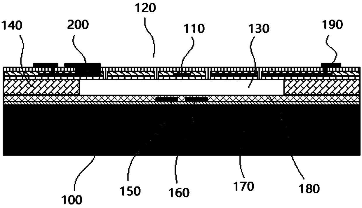
[0056] Specifically, in one embodiment of the present invention, refer to image 3 , the present invention provides a microphone, which includes a first substrate 100 and a diaphragm 120 supported above the first substrate 100 through a first spacer 140, the first substrate 100, the first spacer 140, the diaphragm 102 encloses a vacuum cavity 130 .

[0057] The first substrate 100 of the present invention can be made of single crystal silicon or other materials well known to those skilled in the art, and the first spacer 140 can be formed by layer-by-layer deposition, patterning, and sacrificial processes, and the first spacer 140 can be formed through the first spacer 140 The diaphragm 120 supported on the first substrate 100 and the vacuum chamber 130 can be sealed by, for example, low-pressure plasma-enhanced chemical vapor deposition (PECVD) at 200-350°C. This MEMS process belongs to the common knowledge of those skilled in the art, and will not be described in detail her...

Embodiment 2

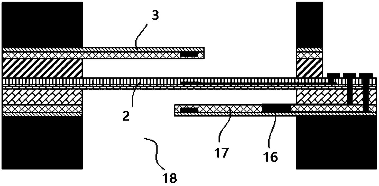
[0078] refer to Figure 4 , the difference from Embodiment 1 is that in this embodiment, the first substrate 100 has a hollow cavity 101 communicating with the outside world, and also includes a cantilever 171 separated from the diaphragm 120, the edge of the diaphragm 120 and the edge of the cantilever 171 The terminals are directly or indirectly connected to the first substrate 100 , so that the diaphragm 120 and the main part of the cantilever 171 are suspended above the cavity 101 in the first substrate 100 .

[0079] The cantilever 171 is separated from the diaphragm 120 by a first spacer, and the height of the first spacer is the initial gap between the diaphragm 120 and the cantilever 171 . Since the structure of the back plate is abandoned, the structural design of the cantilever 171 is adopted, so that the diaphragm 120, the first spacer and the cantilever 171 form an open cavity, and the cantilever 171 will not seal the cavity. This is completely different from the ...

Embodiment 3

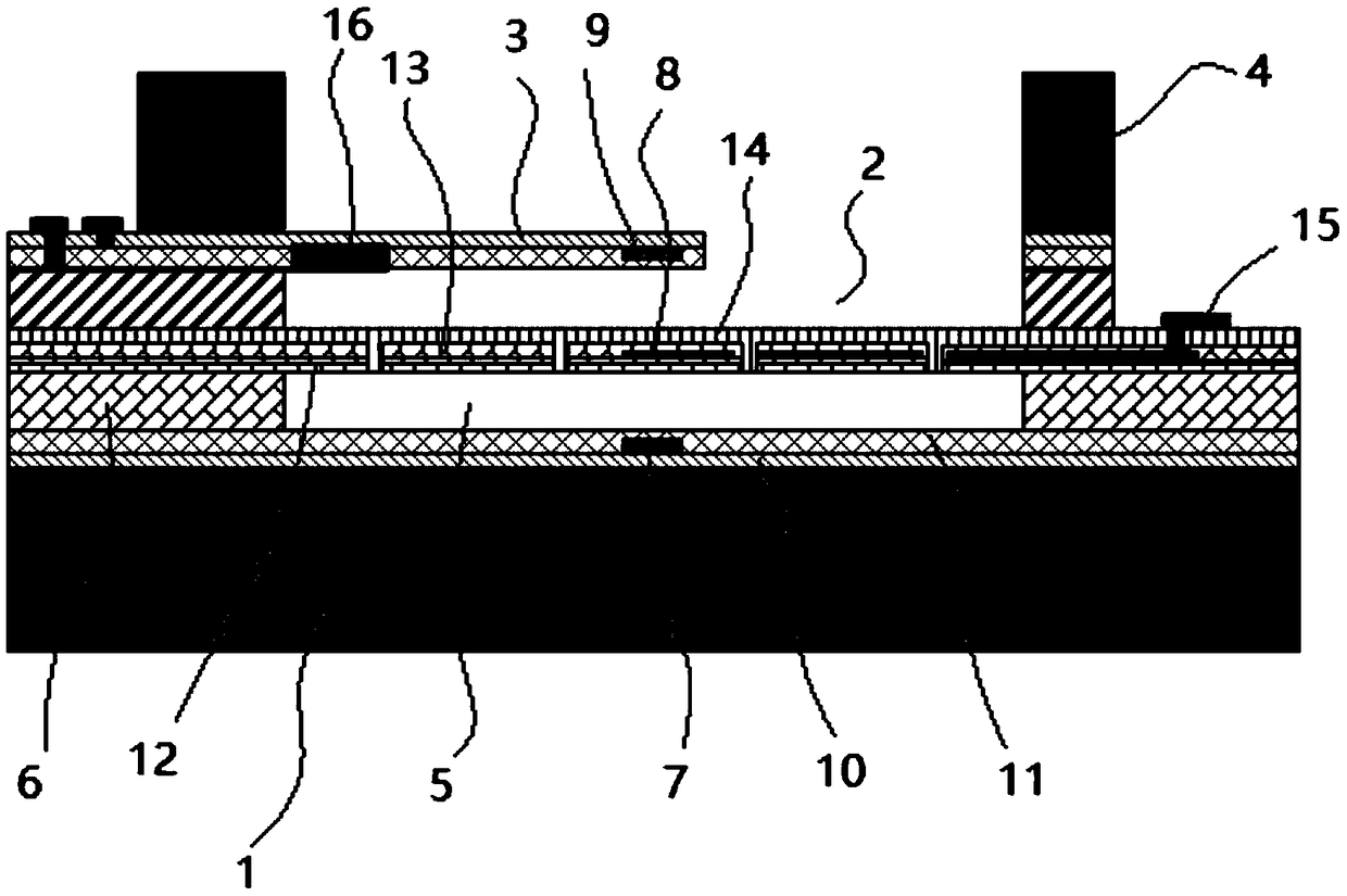
[0091] refer to figure 1 , the present invention provides a microphone, which includes a first substrate 1 and a diaphragm 2 supported above the first substrate 1 by a first spacer 6, the first substrate 1, the first spacer 6, the diaphragm 2 has surrounded the vacuum chamber 5.

[0092] The first substrate 1 of the present invention can be made of single crystal silicon or other materials well known to those skilled in the art, and the first spacer 6 can be formed by layer-by-layer deposition, patterning, and sacrificial processes, and the first spacer 6 can be formed through the first spacer 6 The diaphragm 2 supported on the first substrate 1 and the vacuum cavity 5 can be sealed by, for example, low-pressure plasma-enhanced chemical vapor deposition (PECVD) at 200-350°C. This MEMS process belongs to the common knowledge of those skilled in the art, and will not be described in detail here. Wherein the vacuum chamber 5 is preferably less than 1 kPa, which makes the visco...


PUM


Abstract

The invention discloses a sensor, which comprises a first substrate and a vibrating diagraph supported above the first substrate through a first spacing portion. A detection structure comprises a first magnet, a second magnet and a magnetoresistive sensor arranged in a common magnetic field formed by the first and second magnets. At an initial position, the magnetoresistive sensor is at a positionwhere the magnetic field direction of the first magnet is opposite to the magnetic field direction of the second magnet. The magnetoresistive sensor is configured to sense a change of the common magnetic field of the first and second magnets and output a changing electric signal in a vibration process of the vibrating diaphragm. The sensor further comprises a driving device for regulating the relative positions of the magnetoresistive sensor and each of the first and second magnets. According to the sensor, the relative positions of the magnetoresistive sensor and each of the first and secondmagnets can be finely regulated through the driving device, so that the magnetoresistive sensor can be ensured to work in an appropriate magnetic field, and the influence of manufacturing and assembling errors on the sensitivity of the sensor is avoided.

Description

technical field [0001] The present invention relates to the field of measurement, more precisely, the present invention relates to a sensor, such as a microphone, a pressure sensor, a displacement sensor. Background technique [0002] Existing mainstream sensors, such as microphones, pressure sensors, displacement sensors, etc., are all detected by the principle of flat capacitors. For example, in the structure of the microphone, the plate capacitor includes a substrate and a back plate and a diaphragm formed on the substrate. There is a gap between the back plate and the diaphragm, so that the back plate and the diaphragm form a flat plate The capacitor sensing structure. [0003] In order to take full advantage of the mechanical sensitivity of the diaphragm, the microphone needs to be designed with a large back cavity with ambient pressure to ensure the rigidity of the flowing air far from the diaphragm. The volume of the dorsal cavity is usually much greater than 1mm 3...

Claims


Application Information

Patent Timeline
Patent Type & Authority Applications(China)
IPC IPC(8): G01D5/14
CPCG01D5/14
Inventor 邹泉波冷群文王喆
Owner WEIFANG GOERTEK MICROELECTRONICS CO LTD
Why Eureka
Try Eureka