
A method of suppressing stimulated Raman scattering by fiber laser oscillator

A technology of stimulated Raman scattering and laser oscillator, which is applied in the direction of laser scattering effect, lasers, laser components, etc., can solve the problems of impurity and difficulty in the output spectrum, increase the bandwidth of fiber gratings, etc., and increase the Raman threshold , risk reduction, wide-ranging effects

Active Publication Date: 2019-01-15
NAT UNIV OF DEFENSE TECH
View PDF9 Cites 17 Cited by
  • Summary
  • Abstract
  • Description
  • Claims
  • Application Information

AI Technical Summary

Problems solved by technology

It is still difficult to further increase the bandwidth of fiber Bragg grating due to the limitation of large mode field fiber grating preparation technology
Raman compatibility means that the forward output light of the laser is allowed to contain Raman scattered light, while ensuring that the power of the backward Raman scattered light is within an acceptable range. Although the output power can be further increased, the output spectrum is not pure

Method used


Image

  • A method of suppressing stimulated Raman scattering by fiber laser oscillator
  • A method of suppressing stimulated Raman scattering by fiber laser oscillator
  • A method of suppressing stimulated Raman scattering by fiber laser oscillator

Examples


Embodiment Construction

[0047] Embodiments of the present invention will be further described in detail below in conjunction with the accompanying drawings.

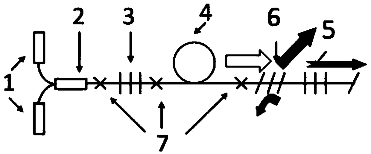
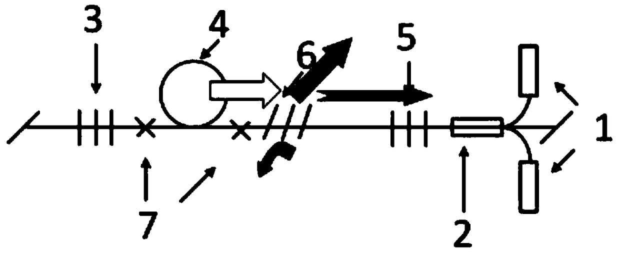
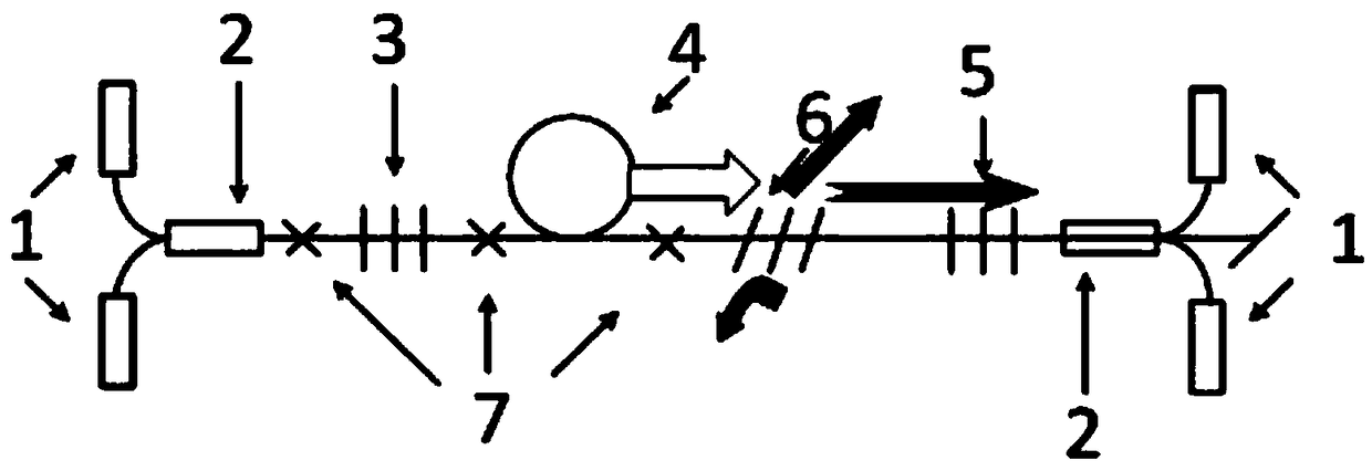
[0048] figure 1 It is a structural schematic diagram of Embodiment 1 of the present invention. In embodiment 1, it is a forward-pumped fiber laser oscillator. figure 2 It is a structural schematic diagram of Embodiment 2 of the present invention. Embodiment 2 is a backward pumped fiber laser oscillator. The setting of the chirped tilted fiber grating in embodiment 2 is the same as that in embodiment 1 except that the pumping method is different from embodiment 1. image 3 It is a structural schematic diagram of Embodiment 3 of the present invention. Embodiment 3 is a bidirectionally pumped fiber laser oscillator. The setting of the chirped tilted fiber grating is the same as that of the embodiment 1 except that the pumping method of the embodiment 3 is different from that of the embodiment 1. The fiber laser oscillators in Examples 1, 2 ...


PUM


Abstract

The invention provides a method for suppressing stimulated Raman scattering by a fiber laser oscillator, wherein the chirped tilted fiber grating is connected into a fiber laser oscillator cavity, andhigh loss of the chirped tilted fiber grating in a Raman band is utilized to suppress the stimulated Raman scattering. The invention utilizes the high loss of the chirped tilted fiber grating in theRaman band, it can suppress the Raman light in the front and back direction of the fiber laser oscillator, Especially for the suppression of backward Raman light, the risk caused by high power backward Raman light to the system is greatly reduced, so that the stimulated Raman scattering phenomenon can be observed in the output of the fiber laser oscillator at a higher power level, and the upper limit of the power output of the fiber laser oscillator is greatly increased.

Description

technical field [0001] The invention belongs to the technical field of fiber lasers, in particular to a method for suppressing stimulated Raman scattering by a fiber laser oscillator. Background technique [0002] Fiber lasers have the advantages of high efficiency, good beam quality, small size, maintenance-free, low operating cost, high beam quality, long operating life, easy modulation, compact structure, etc., and are widely used in military, industrial and other fields. [0003] At present, high-power fiber lasers in the world are all realized by the main oscillator power amplifier (MOPA) structure. In the MOPA structure fiber laser, the mode instability accompanying the increase of the output power seriously limits the beam quality and output power of the fiber laser. In most amplifiers, when the output power of the laser is on the order of hundreds of watts, mode instability occurs, causing high-order modes to occupy most of the power, which seriously degrades the qu...

Claims


Application Information

Patent Timeline
Patent Type & Authority Applications(China)
IPC IPC(8): H01S3/30H01S3/067H01S3/0941
Inventor 王泽锋王蒙王鹏睿胡琪浩李昊奚小明陈子伦王小林许晓军陈金宝
Owner NAT UNIV OF DEFENSE TECH
Learn More