
Hydraulic system with redundancy protection function

A redundant protection and hydraulic system technology, applied in the field of hydraulic systems, can solve problems such as low control accuracy, high hydraulic system failure rate, and poor safety control capabilities

Pending Publication Date: 2019-01-18
DONGFANG ELECTRIC AUTOMATIC CONTROL ENG CO LTD +1
View PDF1 Cites 1 Cited by
  • Summary
  • Abstract
  • Description
  • Claims
  • Application Information

AI Technical Summary

Problems solved by technology

[0004] Aiming at the defects of poor safety control ability, high hydraulic system failure rate and low control precision existing in the hydraulic speed regulation technology of hydropower stations, the present invention discloses a hydraulic system with redundant protection function. Power-on shutdown and power-off shutdown, and at the same time, the unit can be shut down in time when important control components fail, ensuring the normal, stable and safe operation of the equipment

Method used


Image

  • Hydraulic system with redundancy protection function
  • Hydraulic system with redundancy protection function
  • Hydraulic system with redundancy protection function

Examples


Embodiment 1

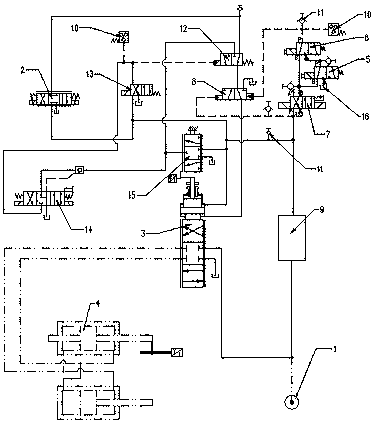
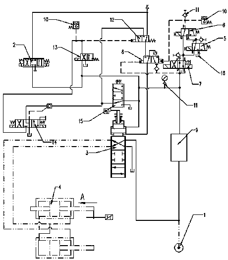
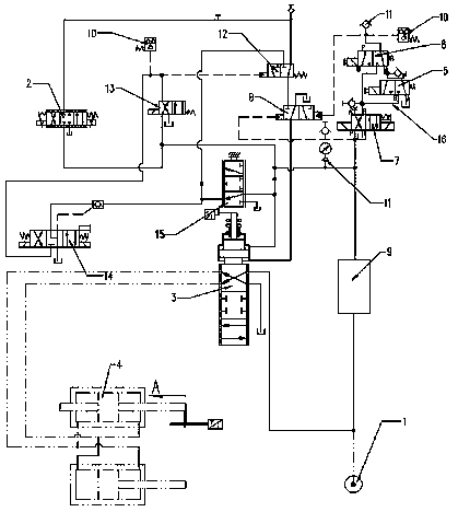
[0032] This embodiment, as a preferred embodiment of the present invention, discloses a hydraulic system for use in redundant protection functions, the specific structure is as follows figure 1 As shown, it includes hydraulic oil source 1, servo proportional valve 2, main pressure distribution valve 3 and guide vane servomotor 4. The main pressure distribution valve 3 is a three-position four-way reversing valve, and the main pressure distribution valve is also set There is a control piston, and a control chamber is provided on both sides of the control piston, wherein the area of ​​the upper control chamber is smaller than the area of ​​the lower control chamber, and the upper control chamber is directly connected with the hydraulic oil source 1 through the hydraulic oil filter 9, thereby forming a constant pressure control chamber; the lower control chamber is connected to the outlet end of the servo proportional valve through the differential pressure hydraulic control rever...

Embodiment 2

[0034]This embodiment, as the best embodiment of the present invention, discloses a hydraulic system with redundant protection function, the specific structure is as follows figure 1 As shown, it includes hydraulic oil source 1, servo proportional valve 2, main pressure distribution valve 3 and guide vane servomotor 4. The main pressure distribution valve 3 is a three-position four-way reversing valve, and the main pressure distribution valve is also set There is a control piston, and a control chamber is provided on both sides of the control piston, wherein the area of ​​the upper control chamber is smaller than the area of ​​the lower control chamber, and the upper control chamber is directly connected with the hydraulic oil source 1 through the hydraulic oil filter 9, thereby forming a constant pressure control chamber; the lower control chamber is connected to the outlet end of the servo proportional valve 2 through the differential pressure hydraulic control reversing valv...


PUM


Abstract

The invention discloses a hydraulic system with a redundancy protection function. The hydraulic system comprises a hydraulic oil source, a servo proportional valve, a main distributing valve and a guide vane servomotor, a differential pressure type hydraulic control reversing valve is arranged between the servo proportional valve and the main distributing valve, one control cavity of the differential pressure type hydraulic control reversing valve is connected with the hydraulic oil source, and the pressure is constant all the time; the other control cavity is connected with the hydraulic oilsource through a first solenoid valve, a second solenoid and a control solenoid valve, wherein inlet ends of the first solenoid valve and the second solenoid valve are connected with the control solenoid valve simultaneously, an outlet end of the first solenoid valve is connected with an inlet end of the second solenoid valve, and an outlet end of the second solenoid valve is connected with the differential pressure type hydraulic control reversing valve. Accordingly, energizing protection and power-lossing protection on a generator set are achieved, and meanwhile the hydraulic system has theadvantages of being high in reaction speed, high in reliability, stable in operation and the like.

Description

technical field [0001] The invention relates to the technical field of hydraulic devices, in particular to a hydraulic system with redundant protection function. Background technique [0002] In the prior art, hydropower stations often adjust the operating speed of the unit through the hydraulic speed control system. Taking the current hydraulic speed control system of hydropower stations at home and abroad as an example, when the unit requires the function of power-off shutdown, the existing system is generally set in the speed control system. A two-position single-coil solenoid valve is implemented. However, if the coil of the solenoid valve is suddenly damaged or loses power abnormally, due to the action of the spring on the single-coil solenoid valve, the solenoid valve will change direction, and the system control oil circuit will change, resulting in abnormal movement of the piston of the main pressure distribution valve of the speed control system. , and then cause t...

Claims


Application Information

Patent Timeline
IPC IPC(8): F15B20/00F03B15/12F03B15/18
CPCF03B15/12F03B15/18F15B20/008F15B2211/8757Y02E10/20
Inventor 王志力贾小平朱廷忠
Owner DONGFANG ELECTRIC AUTOMATIC CONTROL ENG CO LTD
Learn More