Digital-analog converter of successive approximation type

A digital-to-analog converter, successive approximation technology, applied in analog-to-digital conversion, code conversion, instruments, etc., can solve the problems of high switching power consumption and large capacitor array area, and achieve reduced switching power consumption and capacitor array area. Reduced, highly linear effects

Active Publication Date: 2019-01-18
XIDIAN UNIV
View PDF6 Cites 2 Cited by
  • Summary
  • Abstract
  • Description
  • Claims
  • Application Information

AI Technical Summary

Problems solved by technology

[0004] In order to solve the problem of high switching power consumption due to the large capacitor array area of ​​the traditional successive approximation analog-to-digital converter based on capacitor arrays, the present invention provides an ultra-low power consumption successive approximation digital-to-analog converter

Method used


Image

  • Digital-analog converter of successive approximation type
  • Digital-analog converter of successive approximation type
  • Digital-analog converter of successive approximation type

Examples


Embodiment 1

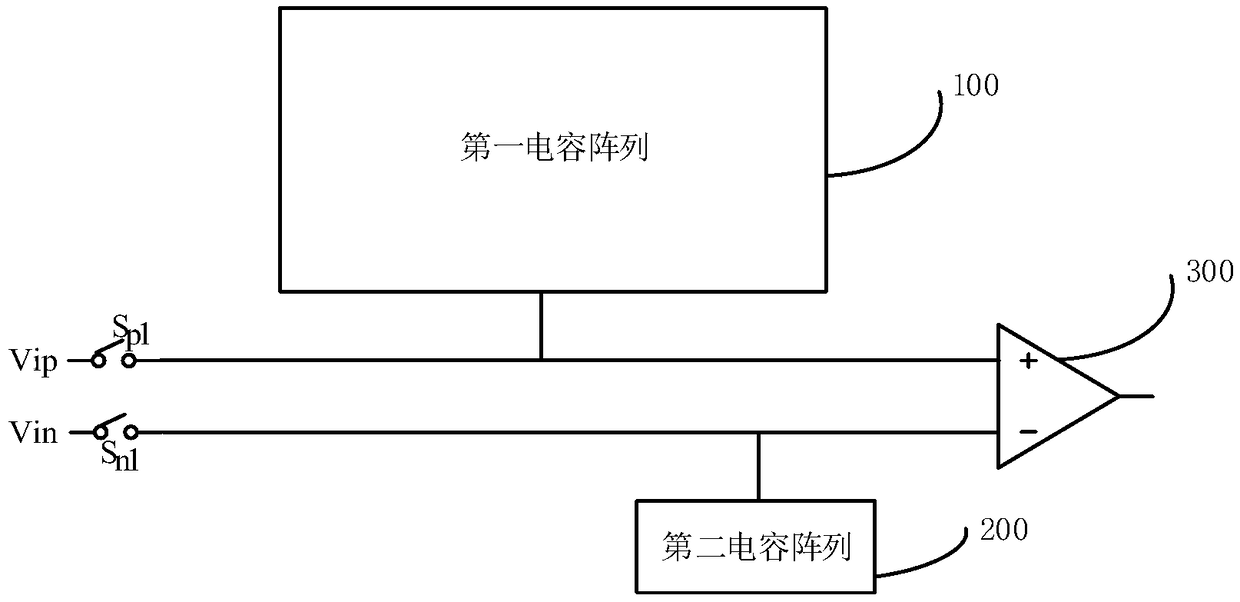
[0035] Such as figure 1 The successive approximation digital-to-analog converter shown includes: a first input terminal Vip, a second input terminal Vin, a first capacitor array 100; a second capacitor array 200, a first switch S p1 , the second switch S n1 and comparator 300, wherein the first input terminal Vip passes through the first switch S p1 It is electrically connected to the non-inverting input terminal of the comparator 300, and the first capacitor array 100 is electrically connected to the non-inverting input terminal of the comparator 300; the second input terminal Vin passes through the second switch S n1 It is electrically connected to the inverting input terminal of the comparator 300 , and the second capacitor array 200 is electrically connected to the inverting input terminal of the comparator 300 .

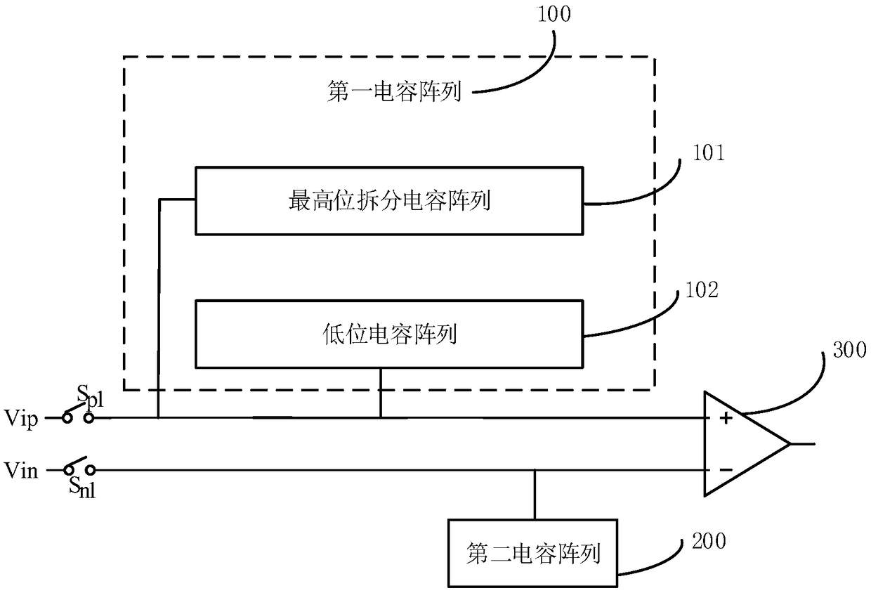
[0036] Such as figure 2 As shown, the first capacitor array 100 includes a highest-order split capacitor array 101 and a low-order capacitor array 102 , and...

Embodiment 2

[0061] Such as Figure 5 to Figure 10 As shown, in this embodiment, the switching sequence of 10 bits is taken as an example, and the 10 bits are compared ten times by successive approximation. The specific instructions are as follows:

[0062] In the sampling phase, the upper plate of the first capacitor array 100 and the upper plate of the second capacitor array 200 sample the input analog signal; after the sampling is completed, the 10th bit is compared, and after completion, the successive approximation control logic is based on the result of the initial comparator 300 Determine b(N), 1≤N≤10, if Vip10>Vin10, b10=1, then control the unit capacitance of the second capacitor array 200 to switch from the common mode voltage Vcm to the power supply potential Vref; if Vip

[0063] In the comparison of the 9th bit, if Vip9>Vin9, the voltage...


PUM


Abstract

The invention relates to a digital-analog converter of a successive approximation type, and the digital-to-analog converter includes a first input terminal, a second input terminal and a first capacitor array; a second capacitor array, a first switch, a second switch, and a comparator, wherein the first input terminal is electrically connected to the non-inverting input end of the comparator through the first switch, and the first capacitor array is electrically connected to the non-inverting input end of the comparator. The second input terminal is electrically connected to the inverting input end of the comparator through the second switch, and the second capacitor array is electrically connected to the inverting input end of the comparator. The invention solves a power consumption problem caused by the excessive area of a switch capacitor array in the conventional time sequence. In addition, the highest bit capacitance splitting and the characteristics of the asymmetric structure itself stabilize the linearity. Meanwhile, the application of a dummy capacitor enables the capacitor area and power consumption to be further reduced.

Description

technical field [0001] The invention belongs to the design field of digital-analog hybrid integrated circuits, and in particular relates to an ultra-low power consumption successive approximation digital-to-analog converter. Background technique [0002] With the promotion of wearable devices and the development of sophisticated biological instruments, the successive approximation analog-to-digital converter (SARADC) has been widely used due to its simple structure and low power consumption. With the development of technology, the energy consumption of tube-level circuits has dropped sharply. In contrast, the main power consumption of SAR ADC comes from the energy consumption in the process of sampling and switching of capacitor arrays. [0003] As for the traditional successive approximation analog-to-digital converter based on the capacitor array, the switching power consumption is very large due to the relatively large area of ​​the capacitor array. How to reduce the are...

Claims


Application Information

Patent Timeline
Patent Type & Authority Applications(China)
IPC IPC(8): H03M1/72
CPCH03M1/72
Inventor 刘术彬韩昊霖阮予丁瑞雪朱樟明杨银堂
Owner XIDIAN UNIV
Why Eureka
Try Eureka