A photonic crystal digital optical switch

A photonic crystal and photonic crystal waveguide technology is applied in the field of optical switches to achieve the effects of increasing reflectivity, improving switching performance, and improving device performance

Active Publication Date: 2022-06-03
江苏长实基业电气科技有限公司
View PDF6 Cites 0 Cited by
  • Summary
  • Abstract
  • Description
  • Claims
  • Application Information

AI Technical Summary

Problems solved by technology

However, this patented technology uses the optical beam splitting realized by multi-mode interference at high power, and its specific splitting effect is related to the heating power, which changes continuously with the increase of the heating power

Method used


Image

  • A photonic crystal digital optical switch
  • A photonic crystal digital optical switch
  • A photonic crystal digital optical switch

Examples


Embodiment Construction

[0026] The optical switch of the present invention has one input port corresponding to two output ports, and two input ports corresponding to one output port.

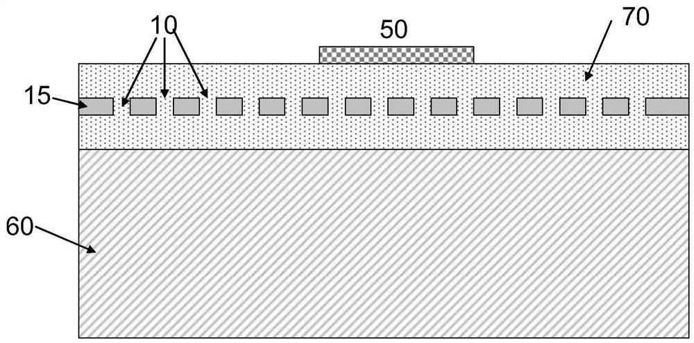
[0027] The angle between the refractive index interface 100 and the photonic crystal waveguide is less than 5 degrees. The photonic crystal waveguide is two

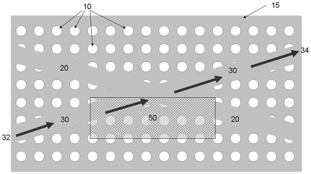
[0028] As shown in Figure 2, the heater does not work, and the signal passes directly through. The signal entering the second entrance 32 of the photonic crystal waveguide is given by

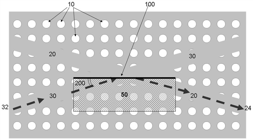
[0029] As shown in FIG. 3, the change in the refractive index caused by the heating of the heater results in the creation of a refractive index interface 100. light here

[0031] Usually, the direction angle of the photonic crystal waveguide relative to the main axis of the photonic crystal structure is a specific integer, such as 30 degrees, 60 degrees, 45 degrees

[0032] The structure of the photonic crystal can be selected from a square lattice, a hexagonal lattice, or any other...


PUM


Abstract

The invention discloses a photonic crystal digital optical switch, which comprises a heater and a cladding layer, a hole-shaped layer is arranged in the cladding layer, and more than two photonic crystal waveguides are arranged on the hole-shaped layer, and the The intersection between the photonic crystal waveguides; the heater is used to heat the area around the intersection of the photonic crystal waveguides, and one side of the heating area is located between the two intersecting photonic crystal waveguides. The photonic crystal waveguide propagates through; when the heater is working, a refractive index interface is formed on the side of the heating area between the photonic crystal waveguides. Optical signals are output from another intersecting photonic crystal waveguide. The extinction ratio and crosstalk of the optical switch of the invention change monotonously with the control signal, and meanwhile, the performance of the device is high.

Description

A photonic crystal digital optical switch technical field The present invention relates to a kind of optical switch, relate in particular to a kind of photonic crystal digital optical switch of total reflection type. Background technique [0002] Usually, the photonic crystal optical switch adopts a directional coupler, a Mach-Zehnder interferometer and other structures. With the processing deviation, Control signal deviation, its extinction ratio, crosstalk, etc. will undergo periodic enhancement-weakening-enhancing-weakening changes. More disadvantageous in use. [0003] Chinese patent 201310603561.6, discloses an optical switch, the optical switch includes a device for carrying the entire The silicon substrate of the structure, the silicon dioxide substrate used to isolate the silicon substrate from the silicon plate, used to form a two-dimensional silicon photonic crystal waveguide, Multimode interference waveguide, silicon slab connected to the waveguide, used to...

Claims


Application Information

Patent Timeline
Patent Type & Authority Patents(China)
IPC IPC(8): G02F1/00G02B6/122
CPCG02F1/009G02B6/122
Inventor 江伟
Owner 江苏长实基业电气科技有限公司
Why Eureka
Try Eureka