Motor apparatus and motor driving circuit

A motor drive and motor technology, which is applied in the field of high-performance motor devices and motor drive circuits, can solve the problems of long starting time and excessive motor current, and achieve the effect of reducing temperature and avoiding damage caused by excessive current.

Inactive Publication Date: 2018-08-17
FAIRWAY ELECTRONICS
View PDF13 Cites 0 Cited by
  • Summary
  • Abstract
  • Description
  • Claims
  • Application Information

AI Technical Summary

Problems solved by technology

However, if the preset current value is set low, the over-current protection mechanism may be triggered frequently when the motor starts due to the large current when the motor starts, causing the motor to start for too long
Relatively, if the predetermined current value is set higher, although it is beneficial to shorten the time for starting the motor, it will also cause the risk of excessive motor current

Method used


Image

  • Motor apparatus and motor driving circuit
  • Motor apparatus and motor driving circuit
  • Motor apparatus and motor driving circuit

Examples


Embodiment Construction

[0070] In order to make the content of the present invention easier to understand, the following specific examples are given as examples in which the present invention can actually be implemented. In addition, wherever possible, elements / components / steps with the same reference numerals are used in the drawings and embodiments to represent the same or similar parts.

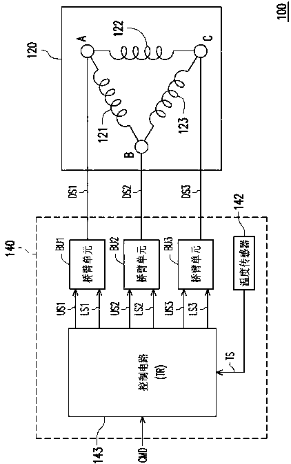
[0071] The motor device proposed in the following embodiments of the present invention can be applied to electrical products such as grinders, hair dryers, range hoods, vacuum cleaners, fans, etc., but is not limited thereto. Please refer to the following figure 1 , figure 1 It is a schematic circuit block diagram of the motor device 100 according to an embodiment of the present invention. The motor device 100 may include a motor module 120 and a motor driving circuit 140 , wherein the motor module 120 may be a multi-phase AC motor module, and the present invention does not limit the number of phases of the mot...


PUM


Abstract

The invention provides a motor apparatus and a motor driving circuit. The motor apparatus includes a motor module and the motor driving circuit. The motor driving circuit includes a plurality of bridge arm units, a temperature sensor, and a control circuit. Each of the bridge arm units is controlled by one of the first PWM signals and one of the second PWM signals generated by the control circuitand outputs a driving signal to drive the motor module. The temperature sensor senses a temperature of the bridge arm units and provides a temperature sensing value to the control circuit. When the temperature sensing value is greater than or equal to a threshold temperature value, the control circuit increases a duty cycle of the first PWM signal of one bridge arm unit and a duty cycle of the second PWM signal of the other bridge arm units, thereby reducing switching power consumption and temperature of the brige arm units.

Description

technical field [0001] The present invention relates to a motor technology, and in particular to a high-performance motor device and a motor drive circuit. Background technique [0002] In the current motor drive technology, pulse width modulation (PWM) control technology is usually used to control the power switch elements in the motor drive circuit, so that the power switch elements provide a drive signal (such as current) to control the motor operating speed. However, when the pulse width modulation signal transitions to cause the power switch element to turn on and off, the power switch element will generate switching power consumption due to frequent turn on and off, causing the temperature of the power switch element to rise. Once the power switch element is overheated, the power switch element can be stopped to cool down, so that the motor will stop running. Another common practice is to use a heat sink to cool down the power switching element. However, providing a ...

Claims


Application Information

Patent Timeline
Patent Type & Authority Applications(China)
IPC IPC(8): H02K11/20H02K11/215H02K11/25H02P29/028H02P29/032
CPCH02K11/20H02K11/215H02K11/25H02P29/032H02P27/085H02P1/46H02P29/02H02P29/68H02P6/14H02P1/12H02P31/00H02K5/10
Inventor 阎宁汉
Owner FAIRWAY ELECTRONICS
Why Eureka
Try Eureka