
An array micro-groove micro-milling cutter

A micro-grooving and micro-milling technology, applied in milling cutters, milling machine equipment, metal processing equipment, etc., can solve the problem of difficult to meet the processing requirements of array micro-grooving with high efficiency, high consistency, and high surface integrity, and poor surface integrity of parts. , poor dimensional accuracy, etc., to achieve the effect of improving stiffness, high surface integrity, strength and stiffness

Active Publication Date: 2020-12-25
INST OF MACHINERY MFG TECH CHINA ACAD OF ENG PHYSICS
View PDF4 Cites 0 Cited by
  • Summary
  • Abstract
  • Description
  • Claims
  • Application Information

AI Technical Summary

Problems solved by technology

[0003] The technical problem to be solved by the present invention is to provide an array micro-groove micro-milling cutter. The core technical problem to be solved is: in micro-milling, due to the easy wear of conventional micro-milling cutters, the surface integrity of the parts is poor, the burrs are serious, and the dimensional accuracy is poor. , it is difficult to meet the processing requirements of array microgrooves with high efficiency, high consistency and high surface integrity

Method used


Image

  • An array micro-groove micro-milling cutter
  • An array micro-groove micro-milling cutter
  • An array micro-groove micro-milling cutter

Examples


Embodiment 1

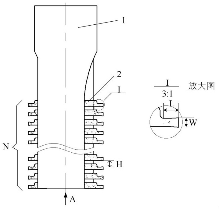
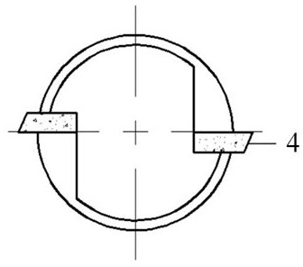
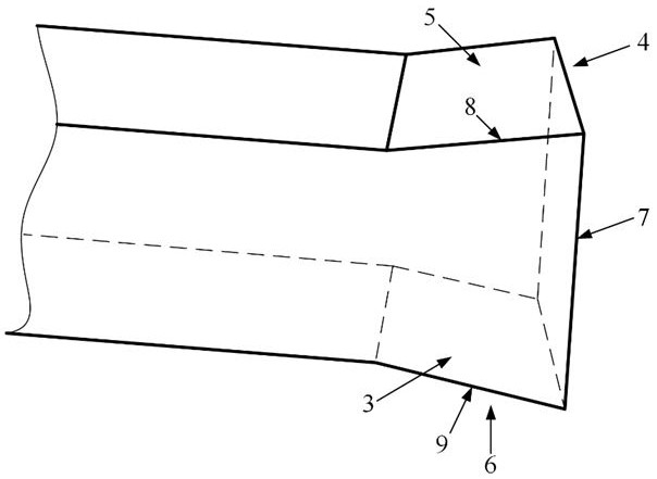
[0032] In this embodiment, microgroove width is 1mm, spacing is 1mm, and array microgroove number is 21. The diameter of tool holder 1 is 30mm, the main cutting edge width is 1mm, the effective milling length is 1mm, and the blade spacing is 1mm. The number of inserts in a single row is 3, the angle between the main flank 4 and the rake face 3 is an acute angle, and the main rake angle, auxiliary rake angle I, auxiliary rake angle II, auxiliary relief angle I and auxiliary relief angle II are all 0 °, the main relief angle is 8°, the handle material is made of carbide, and the blade is made of PCD material.

Embodiment 2

[0034] In this embodiment, the microgroove width is 0.5mm, the spacing is 0.5mm, and the number is 100 array microgrooves. The diameter of the tool holder 1 is 15mm, the main cutting edge width is 0.5mm, and the effective milling length is 0.5mm. The pitch is 0.5mm, the number of inserts in a single row is 50, the included angle between the main flank 4 and the rake face 3 is an acute angle, the main rake angle, the auxiliary rake angle I, the auxiliary rake angle II, the auxiliary relief angle I and the auxiliary flank The angle II is 0°, the main relief angle is 10°, the handle material is made of carbide, and the blade is made of PCD material.

Embodiment 3

[0036] In this embodiment, microgroove width is 0.05mm, spacing is 0.05mm, and array microgroove number is 100. The diameter of tool holder 1 is 5mm, the main cutting edge width is 0.05mm, and the effective milling length is 0.1mm. The pitch is 0.05mm, the number of inserts in a single row is 100, the angle between the main flank 4 and the rake face 3 is an acute angle, the main rake angle, auxiliary rake angle I, auxiliary rake angle II, auxiliary relief angle I and auxiliary flank The angle II is 0°, the main relief angle is 15°, the handle material is made of carbide, and the blade is made of CBN material.


PUM


Abstract

The invention discloses an array microgroove micro-milling cutter. The array microgroove micro-milling cutter comprises a handle and two series of micro-blades which are symmetrically and fixedly mounted at the handle, the handle has a diameter of 5 mm to 30 mm, and a main cutting edge width of the micro-blade is 0.05 mm to 1 mm. The array microgroove micro-milling cutter has the characteristics of high intensity, high rigidity, and high wear resistance, effectively avoids the problems of poor array microgroove precision and consistency due to poor rigidity and easy damage as well as serious burr of the conventional micro-milling cutter, and can realize high efficiency, high consistency, and high surface integrity processing of the array microgroove.

Description

technical field [0001] The invention belongs to the technical field of micromachining, and in particular relates to an array microgroove micro milling cutter. Background technique [0002] The array microgroove structure is a typical microstructure feature, and the feature size is from micron to millimeter. It can realize specific functions such as friction lubrication and optical diffraction through its array structure features. It is widely used in aerospace, biomedical, optical engineering and information technology. communications and many other fields. The processing quality of array microgrooves, such as dimensional accuracy, burr, surface quality, etc. directly affect its performance. Therefore, parts with an array microgroove structure not only need to ensure dimensional accuracy and ultra-high consistency requirements within the range of feature sizes, but also need to meet high surface integrity requirements. In addition, there are a variety of materials for arra...

Claims


Application Information

Patent Timeline
Patent Type & Authority Patents(China)
IPC IPC(8): B23C5/10
CPCB23C5/10
Inventor 钟蠡尹青峰雷天才王志平
Owner INST OF MACHINERY MFG TECH CHINA ACAD OF ENG PHYSICS
Learn More