Device used for separating impurities in waste denitration catalyst and using method of device
A waste denitrification catalyst and impurity technology, which is applied in the field of devices for separating impurities from waste denitrification catalysts, and can solve the problems of unsuitable waste denitrification catalysts, dust collection and dust removal and waste catalyst particles, etc.
- Summary
- Abstract
- Description
- Claims
- Application Information
AI Technical Summary
Problems solved by technology
Method used
Image
Examples
Embodiment 1
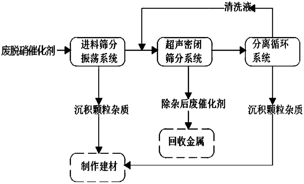
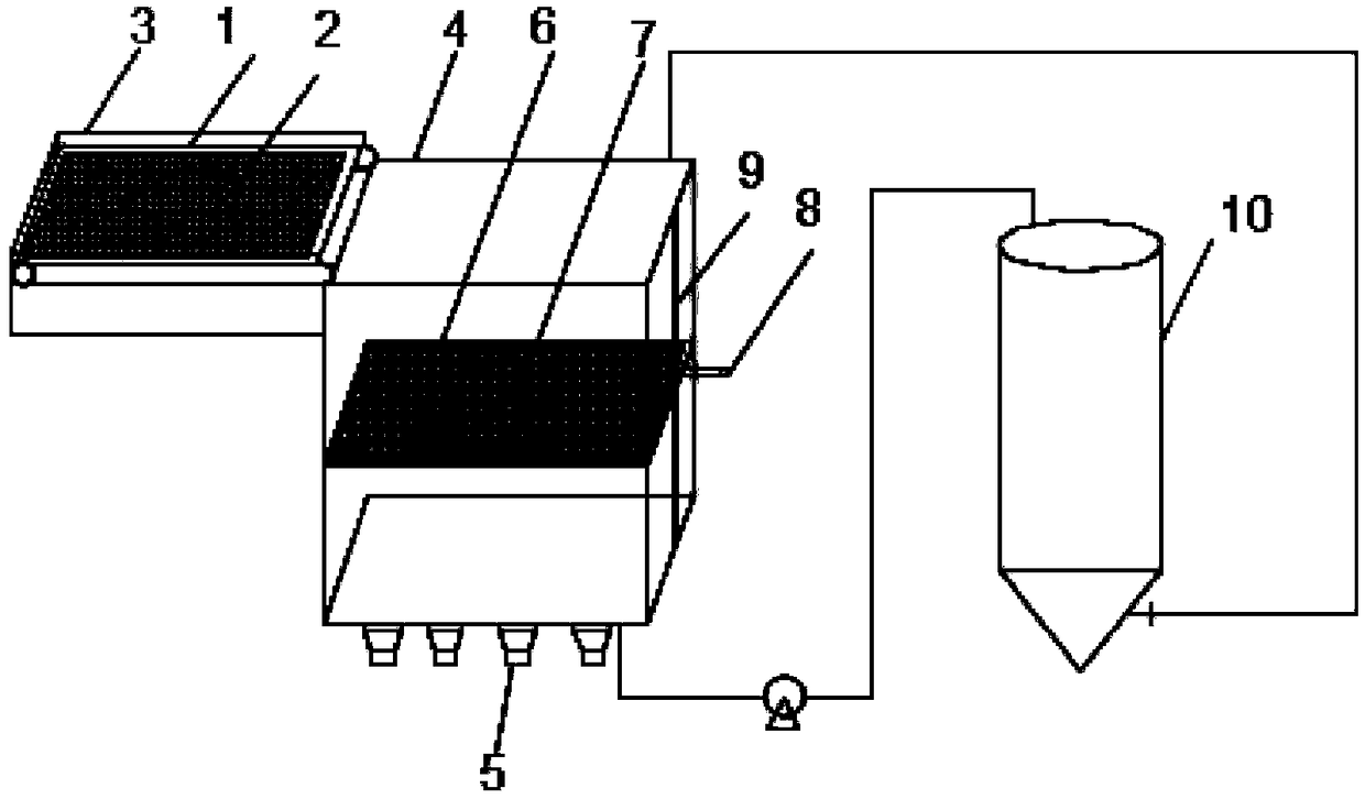
[0058] This embodiment provides a device for separating impurities in spent denitrification catalysts, such as figure 2 shown. The device includes a feeding screening oscillation system, an ultrasonic sealing screening system and a separation circulation system connected in sequence.
[0059] The feed screening oscillation system includes a closed double-layer belt conveyor with a screen structure, which adopts a spiral arrangement and is a point vibration mode; the driving belt 2 of the belt conveyor is made of synthetic fiber screen. The lower end of the transmission belt 2 is equipped with a receiving trough 3, and the transmission belt adopts a slot-fitted and sealed receiving trough 3, and the outlet of the receiving trough 3 is connected to the impurity collection bin.
[0060] The ultrasonic closed screening system includes a cleaning box 4, an ultrasonic atomizer 5 and a sieve plate 6, wherein the cleaning box is connected to the conveyor 1 and the separation circula...
Embodiment 2
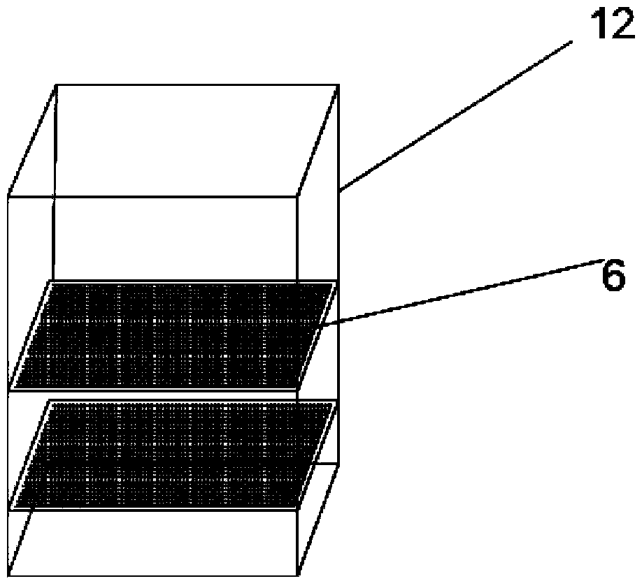
[0069] Compared with Embodiment 1, the ultrasonic airtight screening system described in this embodiment also includes a bubble generator 11, and the bubble generator 11 is arranged at the bottom of the cleaning box 4, and the schematic diagram of its specific device is as follows Figure 4 shown.
[0070] The process flow of using the device in this example to separate impurities in the spent denitration catalyst is as follows:
[0071] (1) Place the spent denitrification catalyst of the honeycomb monolithic structure with structural damage on the conveyor 1 with a screen mesh number of 100 meshes arranged in a spiral shape, the transmission distance of the transmission belt is 50m, and the spent denitrification catalyst is sheet and The powdery mixture adopts the transmission mode of continuous point vibration, and the sedimentation particle impurities are separated during the sieving transmission process. The deposition particle impurities are mainly mullite and quartz phas...
Embodiment 3
[0076] This implementation uses the same device as in Example 2, wherein the waste denitration catalyst is derived from a catalyst with a plate-shaped monolithic structure, and the process flow for separating impurities in the waste denitration catalyst is as follows:
[0077] (1) Place the waste denitration catalyst with structural damage on a conveyor 1 with a screen mesh of 40 meshes arranged in a spiral shape, the transmission distance of the transmission belt is 5m, and the waste denitration catalyst is a mixture of fragments and powders, Using the transmission mode of continuous point vibration, the deposition particles are separated and obtained. The deposition particles are mainly mullite and quartz phase structure ash, containing 45% SiO 2 and 27% Al 2 o 3 ;
[0078] (2) The waste denitrification catalyst that has been preliminarily separated in step (1) enters the ultrasonic closed screening system. The cleaning liquid of the ultrasonic closed screening system is dil...
PUM
 Abstract
Description
Claims
Application Information
 - R&D
- Intellectual Property
- Life Sciences
- Materials
- Tech Scout
- Unparalleled Data Quality
- Higher Quality Content
- 60% Fewer Hallucinations
Browse by: Latest US Patents, China's latest patents, Technical Efficacy Thesaurus, Application Domain, Technology Topic, Popular Technical Reports.
© 2025 PatSnap. All rights reserved.Legal|Privacy policy|Modern Slavery Act Transparency Statement|Sitemap|About US| Contact US: help@patsnap.com


