Shaft end sealing structure of complete tailing paste agitator

A shaft end seal and agitator technology, which is applied in the directions of engine seals, bearing components, shafts and bearings, can solve the problems of high processing and installation requirements, short service life, and increased dynamic clearance of the sealing surface, and achieves load-bearing and fixed Strong heart ability, improve service life, reduce the effect of radial runout

Inactive Publication Date: 2019-01-25
FENY
View PDF7 Cites 1 Cited by
  • Summary
  • Abstract
  • Description
  • Claims
  • Application Information

AI Technical Summary

Problems solved by technology

[0004] When the stirring shaft rotates, the working medium (mortar) easily enters the rotating contact pair with the rotation of the shaft, because the high-load shaft inevitably produces radial runout when stirring and rotating, and this radial runout makes the sealing surface dynamic The gap increases, which leads to increased leakage, and the farther away from the bearing, the greater the radial runout. Therefore, the shaft end seal of a large horizontal mixer faces great challenges due to the radial runout problem
[0005] At present, the more common solution is to adopt the sealing method of mechanical labyrinth seal + packing + floating seal ring. In order to avoid the sealing risk caused by the radial runout of the shaft, the effect of doing so is much better than simply adding a seal on the rotating surface, but the root cause of seal failure, the radial runout, has not been improved. The front packing seal arranged on the rotating surface in this way often has a short service life. After its failure, the extremely fine tailings slurry can easily damage the end face seal of the floating seal ring under the promotion of the rotating motion. In addition, the floating seal ring is due to its own The structural characteristics have high requirements for processing and installation, and it is very inconvenient to maintain and disassemble
Therefore, there are still some deficiencies in this technical route.

Method used


Image

  • Shaft end sealing structure of complete tailing paste agitator

Examples


Embodiment Construction

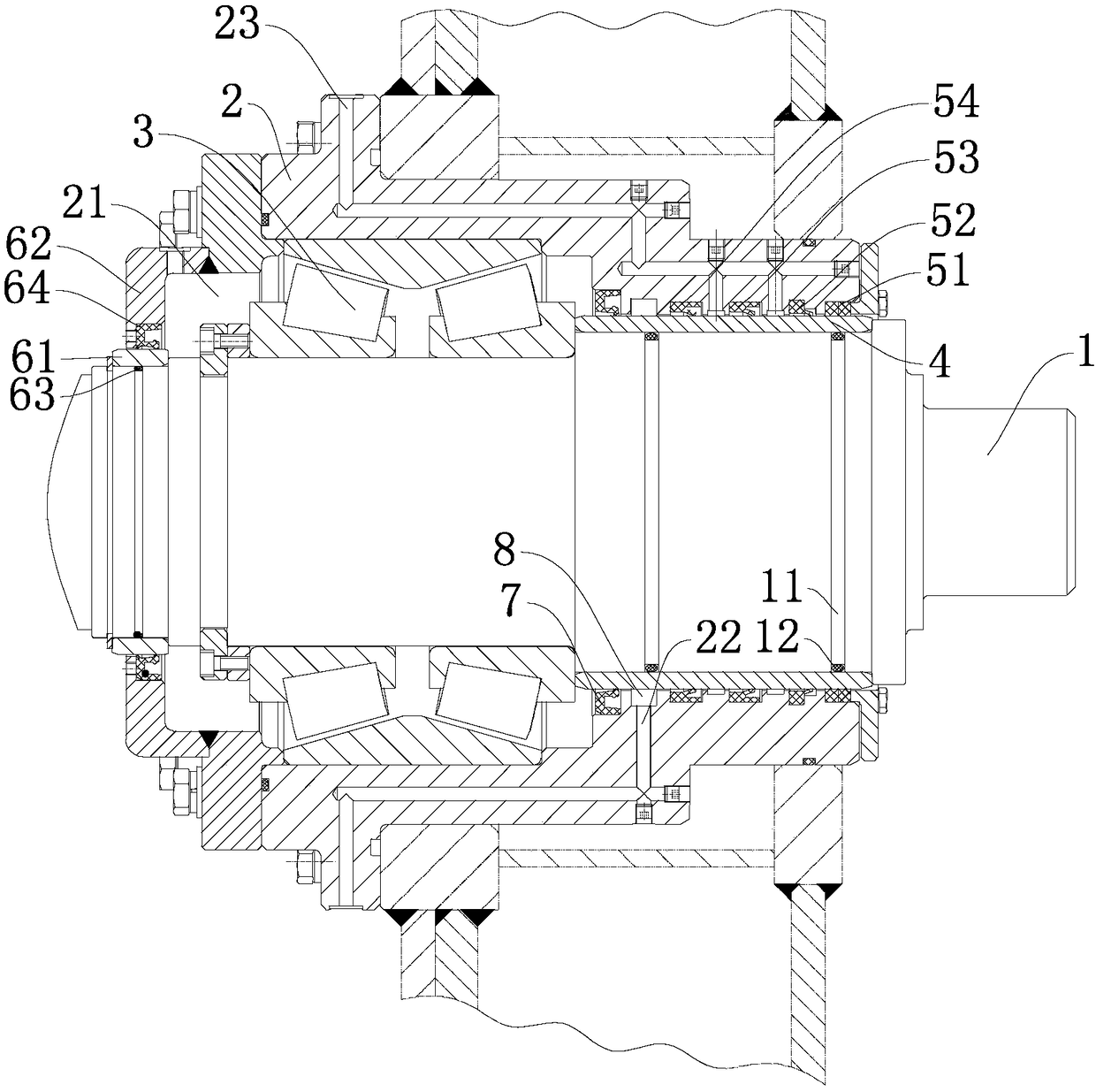
[0018] Such as figure 1 The shaft end sealing structure of the full tailings paste mixer shown includes the stirring shaft 1, the bearing seat 2 sleeved on the stirring shaft 1, the bearing seat 2 is provided with a bearing cavity 21 and a sealing cavity, and the sealing cavity is located in the bearing cavity In front of 21, a double-row tapered roller bearing 3 is fixedly installed in the bearing chamber 21, and the bearing seat 2 is rotationally connected with the stirring shaft 1 through the double-row tapered roller bearing 3, and a rotating sealing assembly is arranged between the sealing chamber and the stirring shaft 1 , The tail end of the bearing seat 2 is provided with a sealing mechanism for sealing the bearing cavity 21 .

[0019] The agitator shaft is supported by double-row tapered roller bearings between the bearing seat and the agitator shaft. The double-row tapered roller bearings have a wide supporting surface and strong load-carrying and centering capabilit...


PUM


Abstract

The invention discloses a shaft end sealing structure of a complete tailing paste agitator. The shaft end sealing structure comprises a stirring shaft and a bearing seat sleeving the stirring shaft, wherein the bearing seat is provided with a bearing cavity and a seal cavity, the seal cavity is located in front of the bearing cavity, a double-row tapered roller bearing is fixedly arranged in the bearing cavity, the bearing seat is rotatably connected with the stirring shaft through the double-row tapered roller bearing, a rotary sealing assembly is arranged between the seal cavity and the stirring shaft, and the tail end of the bearing seat is provided with a sealing mechanism for sealing the bearing cavity. The stirring shaft is supported through the double-row tapered roller bearing between the bearing seat and the stirring shaft, the face width is supported by the double-row tapered roller bearing, the bearing and centering capability is strong, radial runout of the stirring shaft is greatly decreased, accordingly radial runout at a rotary seal face is reduced, and the service life of the sealing assembly is prolonged.

Description

technical field [0001] The invention relates to a full tailings paste mixer, in particular to a shaft end sealing structure of a full tailings paste mixer. Background technique [0002] At present, in the fields of mineral processing, chemical industry, coal washing, wastewater treatment, tailings treatment and other fields, the whole tailings paste mixer is widely used. In these fields, the key equipment of the mixer is related to the structural strength and filling efficiency of the filling material. However, slurry and water leakage at the shaft end often occurs during use, causing wear and damage to shaft end bearings and other components, resulting in failure of some components, resulting in equipment failure and shutdown. Therefore, the shaft end sealing problem of the full tailings paste filling mixer has become an urgent problem to be solved by those skilled in the art. [0003] When the horizontal mixer is working, two sets of seals are often used, the front set i...

Claims


Application Information

Patent Timeline
Patent Type & Authority Applications(China)
IPC IPC(8): F16J15/3204F16J15/40F16C33/78
CPCF16C33/78F16J15/3204F16J15/40
Inventor 邓如欣袁锦红张继文
Owner FENY
Why Eureka
Try Eureka