Optical module test system and method

A technology for optical module testing and light source modules, applied in transmission systems, electromagnetic wave transmission systems, electrical components, etc., can solve problems such as reducing test efficiency, cumbersome testing procedures, and increasing production costs, reducing software management work and enhancing reliability. , the effect of enhancing the efficiency of use

Active Publication Date: 2019-01-25
SUSR COMM TECH
View PDF10 Cites 12 Cited by
  • Summary
  • Abstract
  • Description
  • Claims
  • Application Information

AI Technical Summary

Problems solved by technology

Therefore, the test process is cumbersome in production, and resources such as testers, equ

Method used


Image

  • Optical module test system and method
  • Optical module test system and method
  • Optical module test system and method

Examples


Embodiment Construction

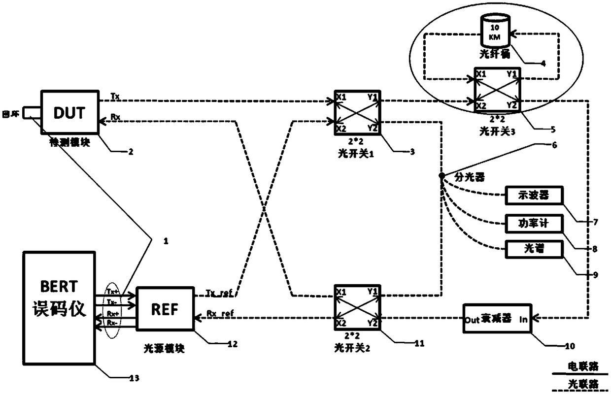
[0020] A kind of optical module test system, such as figure 1 As shown, the equipment list includes:

[0021] serial number

name

serial number

name

1

Coaxial cable

8

dynamometer

2

module under test

9

spectrometer

3

Optical switch 1

10

optical attenuator

4

10Km fiber optic barrel

11

Optical switch 2

5

Optical switch 3

12

Light source module

6

1 / 4 optical splitter

13

BERT

7

oscilloscope

14

/

[0022] The DUT electrical ports Tx+ / - and Rx+ / - of the module to be tested are connected by a coaxial cable to realize a loopback connection, so that the modulated signal generated by the bit error detector is converted from an electrical signal to an optical signal by the light source module, and then transmitted to the module to be tested by the link. The end is converted from an optical signal to an electrical signal and loaded to the transmitte...


PUM


Abstract

The invention discloses an optical module test system and a method thereof. The test system comprises an oscilloscope, a power meter, a spectrometer, an optical attenuator, a light source module and abit error detector. The key test indexes of the optical module, such as optical power, an extinction ratio, a spectrum, a channel cost, an overload, a sensitivity, a receiving/emitting terminal monitoring and the like, are integrated into a test link to realize the test. Compared with the prior art, the invention has the following positive effects: 1, under the condition of guaranteeing the module production and testing, the invention realizes: 1, integrates the testing process of the optical module, reduces the software management work, avoids the risk of the software management, reduces thetesting cost and ensures the testing demand; 2, clever link design enhances the efficiency of the instrument; 3, the relativity between the test indexes is established, which is equivalent to the strict test requirements and enhances the reliability of the test results.

Description

technical field [0001] The invention relates to an optical module testing system and method. Background technique [0002] In the production of optical modules, in order to ensure the quality of the modules, it is necessary to test the key indicators of the modules. Key indicators include: optical power, extinction ratio, spectrum, channel cost, overload, sensitivity, receiver / transmitter monitoring, etc. The existing test method is: the test of the channel cost needs a separate test link to be realized, and other index tests except the channel cost need to build another test link. Therefore, the test process is cumbersome in production, and resources such as testers, equipment, and sites are wasted, which increases production costs and reduces test efficiency. Contents of the invention [0003] In order to overcome the shortcomings of the prior art, the present invention provides an optical module testing system and method, which includes the key test indicators of the ...

Claims


Application Information

Patent Timeline
IPC IPC(8): H04B10/079
CPCH04B10/0795Y02E10/50
Inventor 杨程席文瑶
Owner SUSR COMM TECH
Why Eureka
Try Eureka